LED Part Drivers Documentation 
This page presents an overview of the LED Part Drivers.
A detailed API documentation for the GPIO flavor is available here: LED Part Drivers GPIO API Documentation.
A detailed API documentation for the PWM flavor is also available here: LED Part Drivers PWM API Documentation.
Introduction 
The LED part drivers provide interfaces for external LEDs on the board. It is not directly dependent on the HAL nor the board hardware design. The component driver provides specific unitary services. It can be used by any board to drive external LEDs.
This driver comes as an OpenCMSIS pack. The following section describes the structure of the pack and its usage.
Principles 
There are two flavors of LED control supported by this driver: one using GPIO and another using PWM signals. Each flavor is implemented in a single component.
These two flavors are not exclusive and you can use them together within the same project, providing flexibility to accommodate various hardware configurations and use cases.
This structure enhances the composability and reusability of the driver across different applications.
Programming model 
LED part resources init path
: Initializes activated parts resources either from
system_init()
or user code. The LED resources (GPIO, PWM) are associated with different LED patterns:
LED on GPIO
LED on PWM
LED parts service usage path : The applicative layer invokes LED parts services.
Folder structure 
The driver’s folder structure is as follows:
led
  |- gpio
  |   |- led.h
  |- pwm
  |   |- led_pwm.c
  |   |- led_pwm.h
The driver implements two usage modes:
led.h.
led_pwm.c, led_pwm.h.
Usage and initialization 
PWM variant 
The main data structure for the pwm variant of this driver is the led_pwm_t object structure, which contains all the internal state required by the driver.
The user application never needs to access the fields of this structure directly. However, unlike HAL drivers, the user application has full ownership of the data structures used by part drivers and is responsible for their timely allocation and de-allocation.
The driver has its own object structure, led_pwm_t , to store its specific state and to link to the underlying HAL driver in use.
GPIO variant 
In contrast, the gpio variant does not have an object structure.
At initialization, initialize the resources used by the part drivers separately in the user application, optionally relying on STM32CubeMX2-generated code. The part driver does not enforce the requirements on these resources, but the application must respect them to ensure proper functionality. One of the purposes of STM32CubeMX2 project generation is to assist in this regard. Once all the required resources (HAL instances) are properly initialized, the application may initialize the part drivers and provide those resources.
STM32CubeMX2 configuration and code generation 
Both the GPIO and PWM variants support configuration and code generation in STM32CubeMX2.
PWM variant 
STM32CubeMX2 generates two files for the PWM variant: mx_led_pwm.c and mx_led_pwm.h. The PWM mode of the LED implementation includes the function led_pwm_io_init() , which the driver calls during initialization within led_pwm_init() to properly initialize the necessary structures.
This function uses an ID stored in the led_pwm_t structure to select the appropriate configuration. The generated files may also contain macros specifying the values of various parameters chosen in STM32CubeMX2’s GUI.
To initialize the led_pwm_t structure, extract the TIM handle from the generated TIM file ( mx_tim.h ) and include it in mx_led_pwm.h via mx_hal_def.h .
The LED part drivers may require specific configurations of HAL components to ensure proper functionality, such as:
Timer handle configured for PWM output, using internal clock source, DMA linked to capture/compare requests, and GPIO pin initialized for alternate function.
GPIO variant 
For the GPIO variant, STM32CubeMX2 generates one file: mx_led.h .
The mx_led.h file contains macro definitions for controlling LEDs via GPIO pins, providing convenient functions to turn LEDs on, off, and toggle their state by abstracting the underlying HAL GPIO operations.
The GPIO mode of the LED implementation requires the initialization of a GPIO pin in output mode to drive the LED.
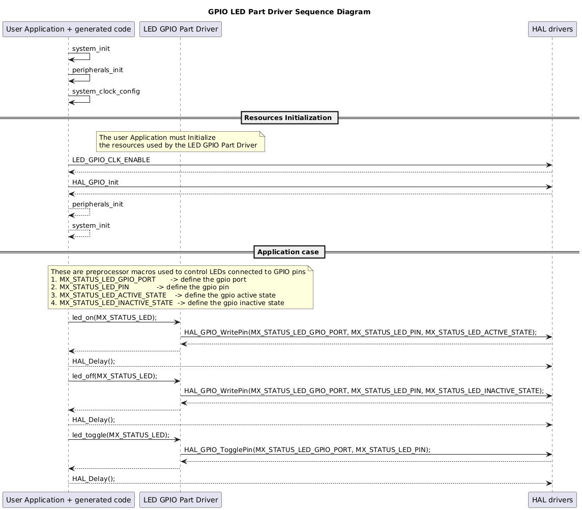
Sequence Diagram 
The diagram below illustrates a simple use case: controlling the LED (on/off and toggle) through the LED driver using GPIO.
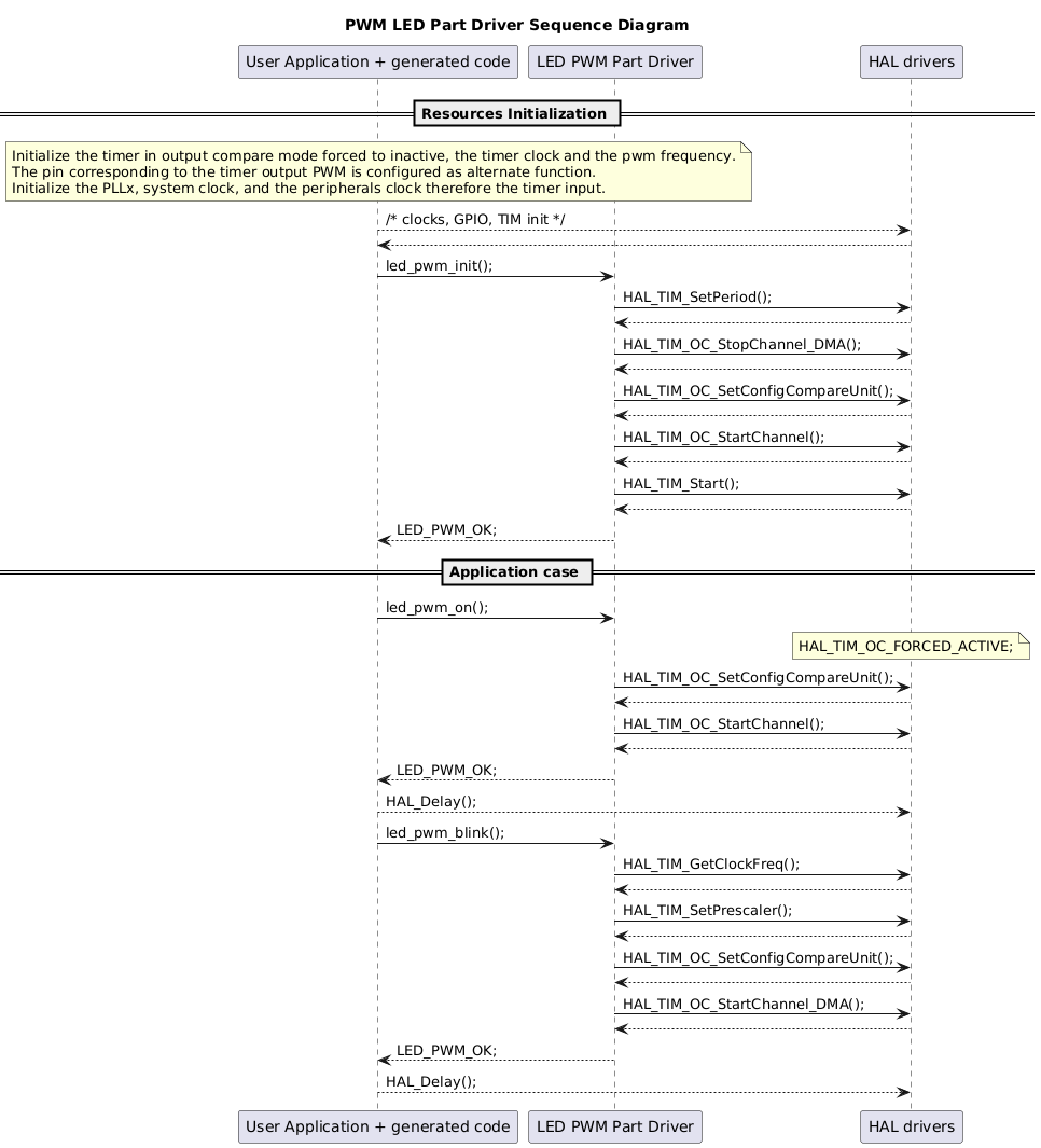
The diagram below presents a simple use case: controlling the LED (on and blinking) using the LED driver through PWM.
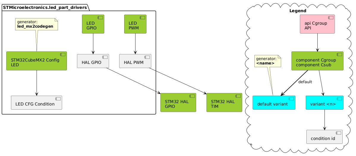
Dependencies 
The diagram below presents the partitioning of this driver into components.
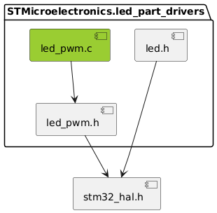
This components’ structure translates to the following inclusion graph in terms of C code: