LIS2DUXS12 Part Drivers

LIS2DUXS12 Part Drivers Documentation 
This page presents an overview of the LIS2DUXS12 Part Drivers.
A detailed API documentation is also available here: LIS2DUXS12 Part Drivers API Documentation - Core.
Introduction 
The LIS2DUXS12 part driver provides APIs to drive LIS2DUXS12 components. The LIS2DUXS12 is a 6-axis IMU (inertial measurement unit) system-in-package featuring a 3-axis digital accelerometer and a 3-axis digital gyroscope. Its implementation is based on the HAL.
This driver is delivered as an OpenCMSIS pack. The structure of the pack and its usage are described in the following sections.
Principles 
This driver is split into three layers:
a “Core” layer containing the high-level algorithms, type definitions, and APIs;
a “Reg” layer containing the low-level algorithms, type definitions, and APIs that are used in the Core layer;
“IO” interface(s) that build a basic level of abstraction between HAL drivers and the Core and the Reg layers.
The scope of the Reg layer is strictly internal; it is not meant to be directly used by the application code. The Reg layer is based on an existing implementation: the code is reused without modification. The scope of the IO interfaces is strictly internal; they are not meant to be directly used by the application code. However, users might develop their own IO interface in order to adapt this driver to a custom environment (non-HAL, mixed HALs…).
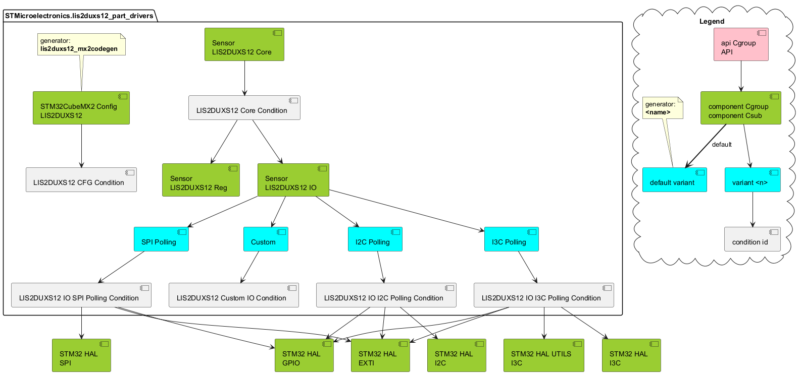
The Core layer is implemented as a single component. Each IO interface is another component. This structure enhances the composability and reusability of the driver in various use cases.
Note: The I/O interfaces are mutually exclusive: only one can be used in a software project.
The IO interfaces currently implemented are:
“i2c”: based on the HAL I2C.
“spi”: based on the HAL SPI.
“i3c”: based on the HAL I3C.
Programming model 
Folder structure 
The driver’s folder structure is as follows:
lis2duxs12
  |- interfaces
  |   |- custom
  |   |   |- lis2duxs12_io.c
  |   |   |- lis2duxs12_io.h
  |   |- i2c
  |   |   |- lis2duxs12_io.c
  |   |   |- lis2duxs12_io.h
  |   |- i3c
  |   |   |- lis2duxs12_io.c
  |   |   |- lis2duxs12_io.h
  |   |- spi
  |   |   |- lis2duxs12_io.c
  |   |   |- lis2duxs12_io.h
  |- regs
  |   - lis2duxs12_reg.c
  |   - lis2duxs12_reg.h
  |- lis2duxs12.c
  |- lis2duxs12.h
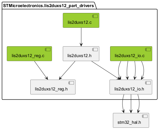
The Core layer is implemented in lis2duxs12.c and lis2duxs12.h. The Reg layer is implemented in lis2duxs12/regs/lis2duxs12_reg.c and lis2duxs12/regs/lis2duxs12_reg.h. IO interfaces are implemented in subfolders of lis2duxs12/interfaces/, in files named lis2duxs12_io.c and lis2duxs12_io.h.
Usage and initialization 
The main data structure for this driver is the
lis2duxs12_obj_t
“object” structure, which contains all the internal state needed by the Core.
The user application never needs to access that structure’s fields directly. However, unlike HAL drivers, the user application has full ownership of the data structures used by the part driver. It is its duty to ensure timely allocation and deallocation.
The IO interface has its own “object” structure,
lis2duxs12_io_t, to store its own specific state.
The layout of that structure is specific to each IO interface, as it is linked to the underlying (HAL) driver being used.
At initialization, the resources used by the part driver must be initialized separately by the user application, optionally relying on STM32CubeMX2-generated code. The requirements for the resources (pin modes, I2C address, …) are not enforced by the part driver but must be respected to ensure proper functionality. One of the purposes of CubeMX’s project generation is to assist in this regard. Once all the required resources (HAL instances) are properly initialized, the part driver initialization may be called and given those resources.
STM32CubeMX2 configuration and code generation 
STM32CubeMX2 generates two files, mx_lis2duxs12.c and mx_lis2duxs12.h.
These files contain an implementation of
lis2duxs12_io_init(), which is called by the LIS2DUXS12 driver during initialization (inside
lis2duxs12_drv_init()) to initialize the
lis2duxs12_io_t
structure.
The function uses an ID stored in the
lis2duxs12_io_t
structure to discriminate the configuration that will be used.
They may also contain macros specifying the values of the various parameters chosen in STM32CubeMX2’s GUI.
Most values used to initialize the
lis2duxs12_io_t
instances are extracted from the HAL-generated init code, mainly mx_hal_def.h.
The specific settings available to users depend on the IO interface that was selected.
For the I2C IO interface, the following parameters are available:
I2C handle to use
The SA0 pad selection. It can be set to either GND or VDD to change the device’s address, enabling multiple devices to share the same I²C bus without address conflicts.
The first interrupt pin selection. It is optional and can be used to send an interrupt signal from the device to the MCU.
The second interrupt pin selection. It is optional and can be used to send an interrupt signal from the device to the MCU.
For the I3C IO interface, the following parameters are available:
I3C handle to use
The SA0 pad selection. It can be set to either GND or VDD to change the device’s static address, enabling multiple devices to share the same I3C bus without address conflicts.
The dynamic address selection. It can be set according to the needs of the application.
The ENTDAA selection. It can be set if the application uses the ENTDAA broadcast messages for dynamic address assignment, otherwise the driver uses the SETDASA message internally to set the dynamic address.
The first interrupt pin selection. It is optional and can be used to send an interrupt signal from the device to the MCU.
The second interrupt pin selection. It is optional and can be used to send an interrupt signal from the device to the MCU.
For the SPI IO interface, the following parameters are available:
SPI handle to use
CS pin selection. It is used to select the device when the SPI bus is shared.
The first interrupt pin selection. It is optional and can be used to send an interrupt signal from the device to the MCU.
The second interrupt pin selection. It is optional and can be used to send an interrupt signal from the device to the MCU.
The LIS2DUXS12 part driver may impose a specific configuration on HAL components in order to guarantee their functionality.
For the I2C IO interface, the following constraints are applied:
I2C handle configured in polling mode
For the SPI IO interface, the following constraints are applied:
SPI handle configured in polling mode
Sequence Diagrams 
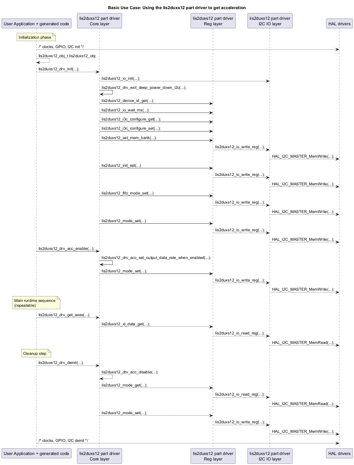
The diagram below presents a simple use case for this driver.
Dependencies 
The diagram below presents the partitioning of this driver into components.
This components’ structure translates to the following inclusion graph in terms of C code: