README 
The README file is the first file that you should read when you open an example project. It describes the example scenario, the hardware setup, and guides you through the example code.
How to display the README file? 
The README file is a Markdown file that can be opened with any text editor. The best user experience is to open it with a Markdown viewer, for example the Markdown preview in Visual Studio Code.
In a Markdown viewer, you can easily spot badges redirecting you to this user manual and hyperlinks to additional documents. You can also visualize pictures and diagrams:
-
Signals representation
-
Pinout diagrams
-
UML diagrams ( Learn more about UML )
What is in this file? 
The README file contains the following sections:
|
Section |
Purpose |
|---|---|
|
Introduction |
Provides an overview of the example project (“How to…” description of what the example demonstrates). |
|
Detailed scenario |
Describes the example scenario step by step. Each step is a functional block that can be found in the code. This section can also provide diagrams, reference applicative logs, and illustrations of how the example behaves. |
|
Example configuration |
Describes the software configuration implemented in this example. These are the key elements to make sure the STM32 microcontroller is properly configured to run the demonstrated use-case. |
|
Hardware environment and setup |
This section describes the generic hardware setup of the example. A wiring diagram is provided to illustrate the connections between the STM32 microcontroller and the peripherals. A pinout table is also provided to help you identify the pins used in the example, with their associated labels used in the code. It also provides the hardware constraints to respect (for example, pull-up resistors or clocks). Any device specific information is provided in this section. |
|
Troubleshooting |
This section provides the common points of attention, issues, and their solutions. It also provides some useful information to ensure the proper operation of the examples (for example, timeout values). |
|
See also |
This section provides links to other documents that can help you understand the example and go further with the demonstrated features. It also references other examples dealing with the same topic. |
|
License |
This section provides the license of the example project. |
Some of these sections contain a badge redirecting you to the proper section of this user manual to get more general information.
|
Badge |
Purpose |
|---|---|

|
This is the “Read the User Manual” badge, redirecting to the home page of this user manual. |

|
This is the “Configure” badge, redirecting to the configuration page of this user manual. |

|
This is the “Troubleshooting” badge, redirecting to the debug page of this user manual. |

|
This is the “Go further” badge, redirecting to the “Get more” page of this user manual. |
How to find it in the code? 
The README file links the description of the applicative scenario to the code thanks to the steps of the “Detailed scenario” section.
Writing conventions 
Both in the README and in the code, we apply the following writing conventions to clearly identify what we are talking about:
|
Convention |
Example of use |
Purpose |
|---|---|---|
|
Third-person tense in the README. |
Step 1: Initializes the flash instance and unlocks the access to the flash control register. |
This is the description of the step. It describes what this scenario step covers, not what the user has to do. The third-person tense clarifies we describe a functionality that can require a set of operations. |
|
Third-person tense in the code. |
brief: Checks the correctness of the data when the transfer is completed. |
This is the description of the service that a function provides. The third-person tense clarifies we describe a functionality that can require a set of operations in its implementation. |
|
Imperative form. |
Enable the FPU interrupt in the NVIC |
This is the explanation of what the code is doing for a particular operation. The imperative clarifies that we describe one precise action, not a service. This is like giving a specific order to the system. |
Detailed explanations 
The README file can provide detailed explanations of the example scenario when needed.
Example behavior 
The README file can provide a very precise description of the behavior of the example scenario.
A UML sequence diagram explains the dynamic sequence of the example scenario when required. The steps of the scenario are indicated in the diagram, so you can easily connect it to the textual description in the README and the code in the C files. For example, the diagram below shows the expected sequence of an I2C board to board communication.

A signal diagram shows the expected signal produced by the example scenario. For example, the diagram below shows the expected sinusoidal signal of an ADC example.

When an example implements applicative logs, the README shows the expected logs. For example, the logs snippet below shows the expected logs of an I2C board to board communication.
[INFO] Step 1: Device initialization COMPLETED.
[INFO] Controller - Tx/Rx Buffers IDENTICAL. Transfer COMPLETED of I2C Two Boards Communication - Message A
[INFO] Controller - Tx/Rx Buffers IDENTICAL. Transfer COMPLETED of I2C Two Boards Communication - Message B
[INFO] Controller - Tx/Rx Buffers IDENTICAL. Transfer COMPLETED of I2C Two Boards Communication - Message A
[INFO] Controller - Tx/Rx Buffers IDENTICAL. Transfer COMPLETED of I2C Two Boards Communication - Message B
Example configuration 
The main information about the example configuration is provided in the Example configuration section. It is complemented by hardware specific information in the Hardware environment and setup section. The Troubleshooting section provides additional information about some points of attention to ensure the proper operation of the example.
For example, if we look at the configuration of a PWM output example, we can see the following information in the README file:
This section summarizes the configuration of the TIM peripheral. It also gives the generic rules to compute the PWM frequency and duty cycle.
The timer's autoreload register (ARR) defines the PWM period in number of timer counter clock (tim_cnt_ck) cycles.
The ARR value is chosen as indicated below:

    PWM period = tim_cnt_ck period * (ARR + 1)
    PWM frequency = tim_cnt_ck frequency / (ARR + 1)
    ARR = (tim_cnt_ck frequency / PWM frequency) - 1
A collapsed section can be expanded to see the numerical calculations:
To set a PWM output frequency to 24kHz with a 1MHz timer counter clock:

    ARR = (1 MHz / 24 kHz) - 1
    ARR = (1000000 / 24000) - 1 = 40.66
    ARR = 40 (integer rounded down to fit into the register)
This section provides hardware specific information, for each supported STM32 series and baord.
For instance, it can describe the peripherals clocks and demonstrate some precise calculations for the chosen hardware:
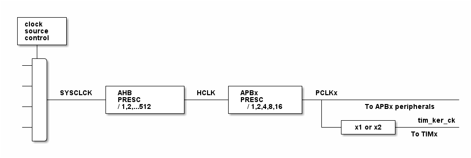
In this configuration:

- The HCLK is set to 160MHz.
- The timer counter clock is set to 1 MHz.

To obtain a timer counter clock at 1MHz with the APB prescaler set to 1 and the HCLK set to 160MHz, the timer prescaler must be:

      timer_prescaler = (160 MHz / 1 MHz) - 1 = 159
Specific points of attention are highlighted, for example:
__System clock__: The timer clock depends on the system clock configuration. Changing the CPU clock or the peripheral bus' clock affects the PWM frequency and duty cycle.50%.
See also section 
The See also section provides links to other documents that can help you understand more broadly the example topic and go further with the demonstrated features:
-
Application notes
-
User manuals
-
Reference manuals
-
Other examples related to the same topic
It goes beyond the specific example and allows enlarging the view of a particular topic.