
 STM32CubeMX2

How to get started with STM32CubeMX2 
LED toggle example 
Project creation 
Device selection 
From the Home view, click on Board to initiate a board-based project
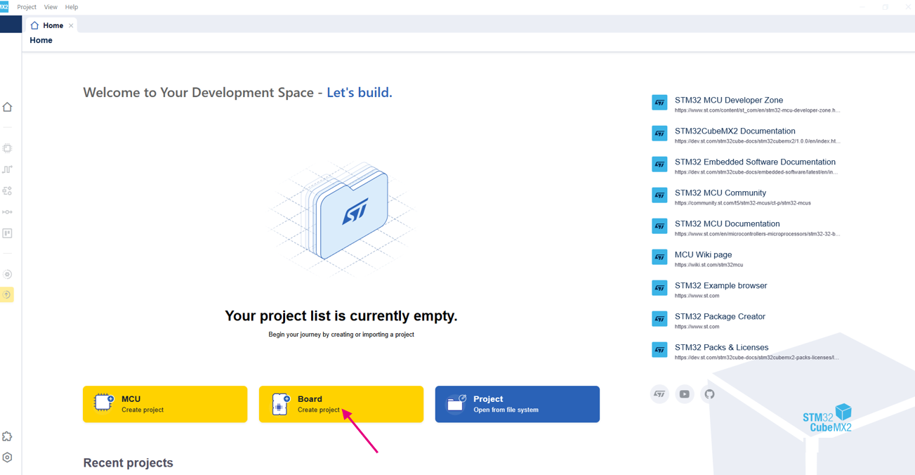
Create a project from a board 
Select the board (1): For this example , we use NUCLEO-C562RE.
Click Continue to provide the project details (2).
Enter the project name (3): example Toggle_LED.
Specify the project location (4): example C:\Projects.
Click Automatically Download, Install & Create Project (5).
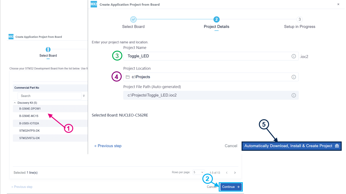
Project setup 
After creating the project, open Project settings to display and manage the project. This tab contains the following:
Project settings (1): Displays the project settings, including the project name, location, selected device and the software project.
IDE project generation settings (2): Manages the IDE project. See the IDE project generation for more details.
Left bar (3): contains quick access icons for frequently used features. See Menu bar and left bar for further details.
Packs management (4): Manages the installed packs.
- Global services settings (5): Manages the global services settings.
HAL System init settings (6): Manages Code Generation parameters for common System files.
HAL Common definitions (7): Manages Code Generation parameters for Core Files.
For this tutorial, only the pinout configuration is required.
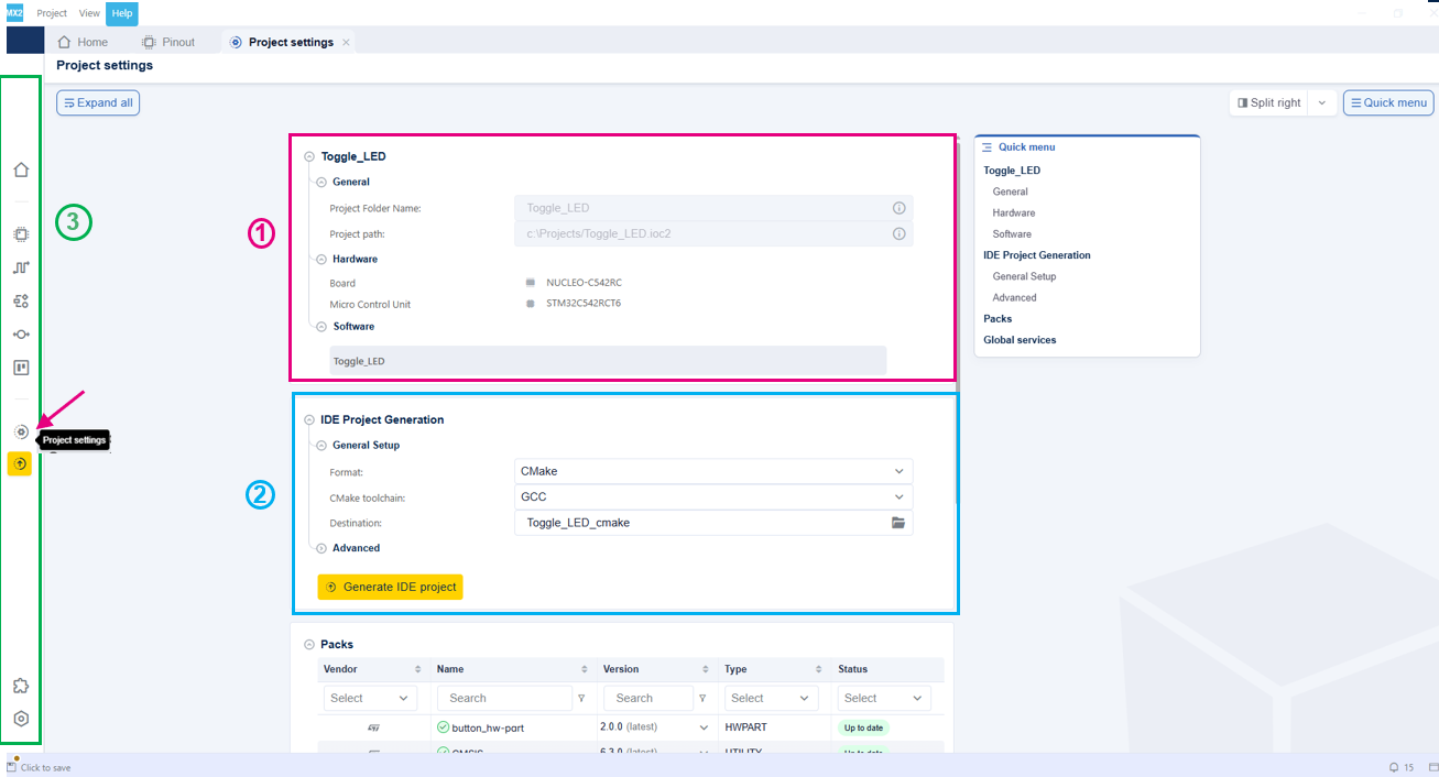
Project & IDE project settings 
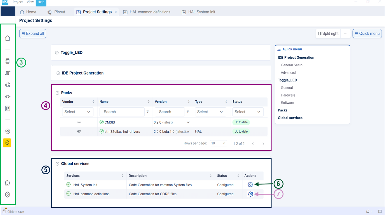
Packs management & Global services settings 
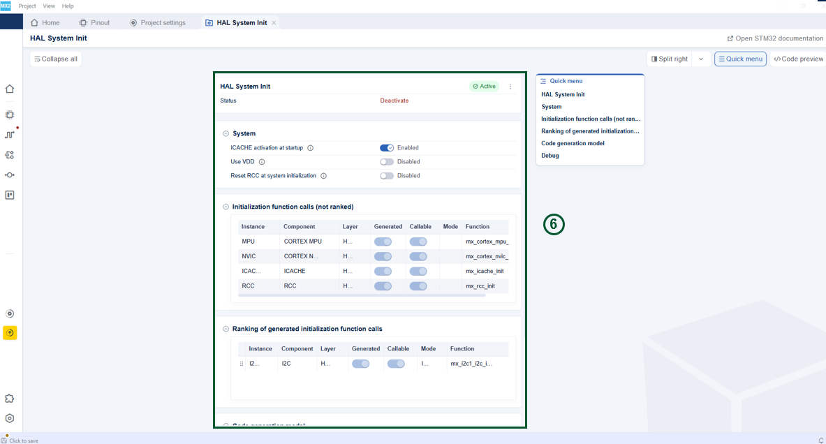
HAL system init settings 
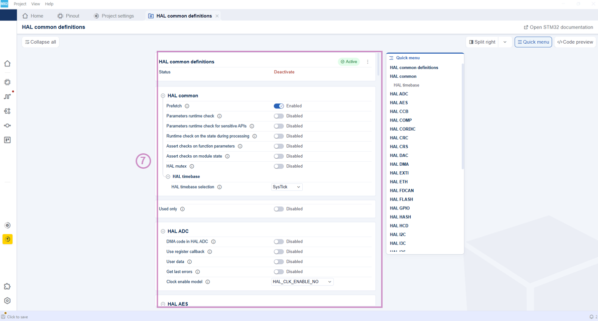
HAL common definitions 
Pinout assignment 
Open the pinout view (1): Click on its icon from the left bar.
Locate PA5 (2): Use the search function to find its location. PA5 is the GPIO that is connected to the LED we want to use on this NUCLEO board.
Note
The Reset Pinout action clears reserved and GPIO signals while preserving peripheral-configured signals and user labels.
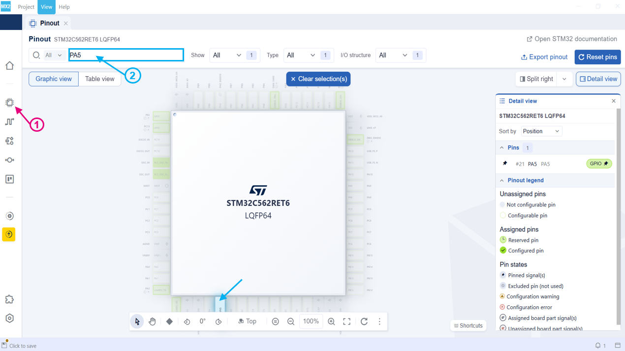
Pinout view 
Assign PA5 to GPIO (3): Right-click the pin and select Assign signal > GPIO.
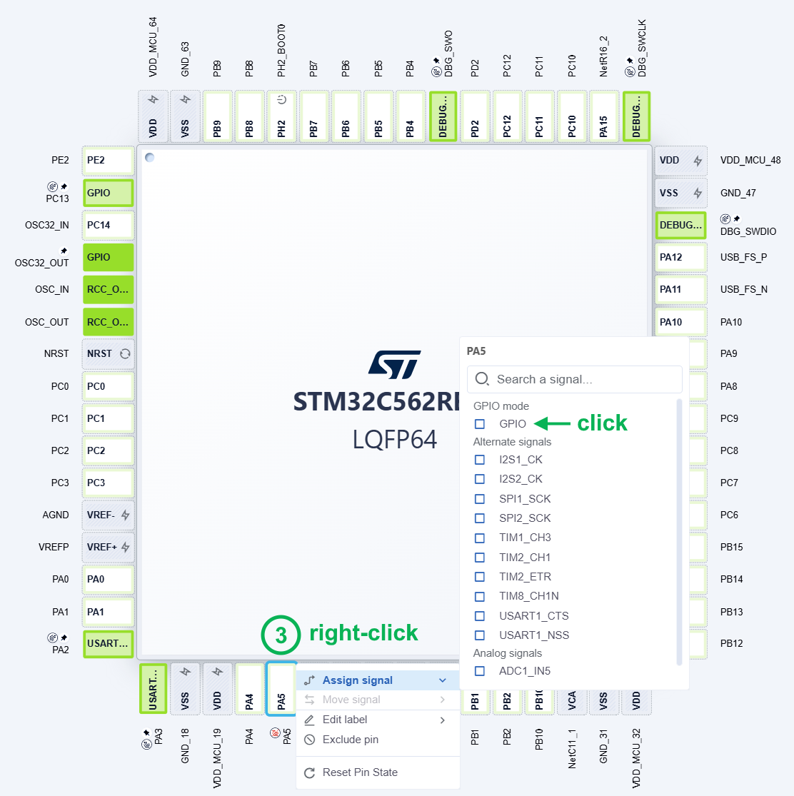
Pinout configuration 
Note
The table view can also be used to configure pins. See Pinout for further details.
GPIO configuration 
To configure GPIO component:
Open the configuration (1): Right-click on the pin and select Configure GPIO.
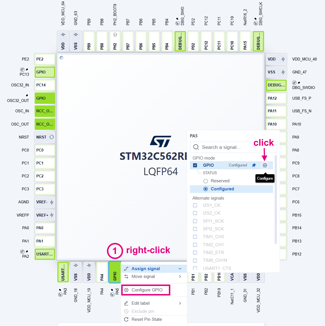
Access to GPIO configuration 
Locate the pins PA5 (2): Extend the Pins section to find the pins.
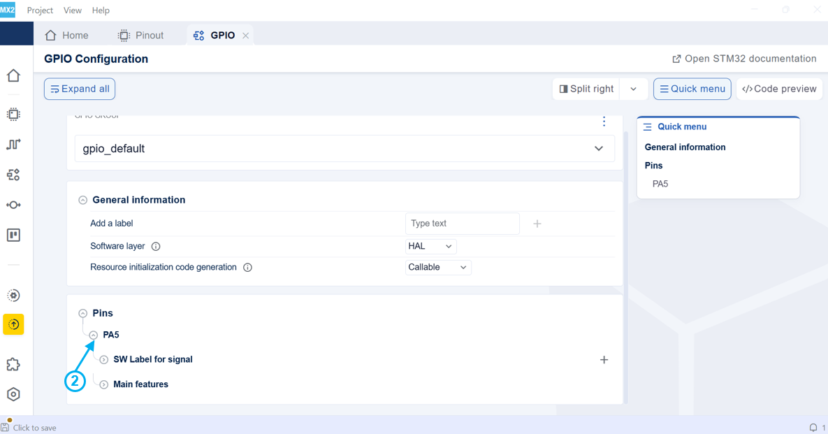
GPIO configuration 
Set PA5 mode to output (3): Extend the configuration then change the mode to output.
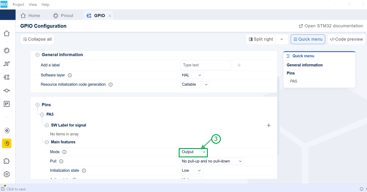
PA5 pin configuration 
IDE project generation 
Project generation 
After configuring PA5 pins, follow these steps to generate the IDE project:
Select format (1): Choose the desired format. Available formats include IAR Embedded Workbench for ARM, CMake and Open-CMSIS. The default is CMake.
Select toolchain (2): A default toolchain is automatically created. However, the Open CMSIS format currently supports multiple toolchains. In this case, the user can explicitly choose GCC or IAR instead of the default AC6.
Select destination (3): Browse and select the folder for the IDE project. The default path is at the root folder of the created STM32CubeMX2 project.
Generate IDE project (4): Click the Generate button to create the IDE project.
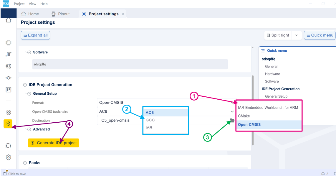
Project settings 
Note
The Show on disk option allows you to view the generated files on your disk when the IDE project generation is completed.
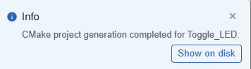
Check the IDE project generation to learn more about the advanced settings.
Unified CLI workflow 
This section groups all command-line operations used in the tutorial: board-based project creation, pin assignment, GPIO configuration, and IDE project generation.
Create the project from a board
Use
cube


              mx


              project


              create-from-board
to create a new STM32CubeMX project based on a board CPN (Commercial Part Number).
cube mx project create-from-board \
--cpn NUCLEO-C562RE  \
--project-location /c/Workspace_MX2/MySecondCLIProject \
--project-name Toggle_LED
Arguments:
--cpn: Board identifier (e.g.NUCLEO-C562RE).--project-location: Base folder where the project will be created.--project-name: Logical project name.
After this step, an
.ioc2
file is created, for example:
/c/Projects/Toggle_LED.ioc2
Assign or unassign a pin signal
You can modify pin assignments using the
cube


              mx


              pinout
commands.
Unassign a signal from a pin
cube mx pinout unassign-signal \
  -p /c/Workspace_MX2/MySecondCLIProject/Toggle_LED.ioc2 \
  --pin PA5 \
  --signal GPIO
Arguments:
-p: Path to the.ioc2configuration file.--pin: Pin name (e.g.PA5).--signal: Currently assigned signal type to remove (e.g.GPIO).
Assign a signal to a pin
cube mx pinout assign-signal \
-p /c/Workspace_MX2/MySecondCLIProject/Toggle_LED.ioc2 \
--pin PA5 --signal GPIO
This assigns the
GPIO
function to pin
PA5
in the project configuration.
Configure GPIO parameters
Use
cube


              mx


              sw-config
to set software configuration parameters, such as pin modes.
cube mx sw-config set-parameter-value \
-p /c/Workspace_MX2/MySecondCLIProject/Toggle_LED.ioc2 -r GPIO \
--parameter-path pins/0/basic/mode -v OUTPUT
Arguments:
-r GPIO: Selects the GPIO configuration resource.--parameter-path: Path of the parameter in the configuration tree (for examplepins/0/basic/mode).-v OUTPUT: Sets the parameter value (mode) toOUTPUTfor that pin entry.
Note
The exact
parameter-path
may depend on the project structure
(pin index, naming, and mode options).
Generate the IDE project
Generate buildable project files using
cube


              mx


              ide-project


              generate
.
cube mx ide-project generate \
-p /c/Workspace_MX2/MySecondCLIProject/Toggle_LED.ioc2 \
--format CMake --build-target .debug_GCC+NUCLEO-C562RE \
--source include-packs-from-local --destination /c/Workspace_MX2/MySecondCLIProject/Toggle_LED_cmake
Arguments:
--format CMake: Generates a CMake-based project.--build-target: Name of the build configuration/target (for example.debug_GCC+NUCLEO-C562RE).--source include-packs-from-local: Use installed local packs as source.--destination: Output folder for the generated CMake project.
After this step, you can open or build the generated project from:
/c/Workspace_MX2/MySecondCLIProject/Toggle_LED_cmake
Project opening 
Navigate to the project’s location:
Project location (1): The project is located at C:\Projects.
Project configuration file (2): This .ioc2 file is the main configuration file for the STM32CubeMX2 project.
IDE project folder (3): Contains the IDE-specific files and folders.
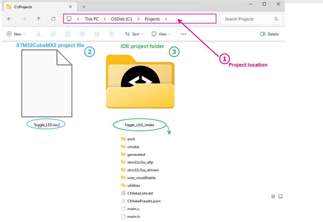
Project directory 
Open Toggle_LED project with STM32CubeIDE for VSCode, and edit the main.c file.
Write the application code (1): In the main function, add the highlighted code to toggle GPIO pins with delays.
Build the code (2): Click the Build button to compile the code.
Run the code (3): Click the Launch button to execute the code on the target hardware.
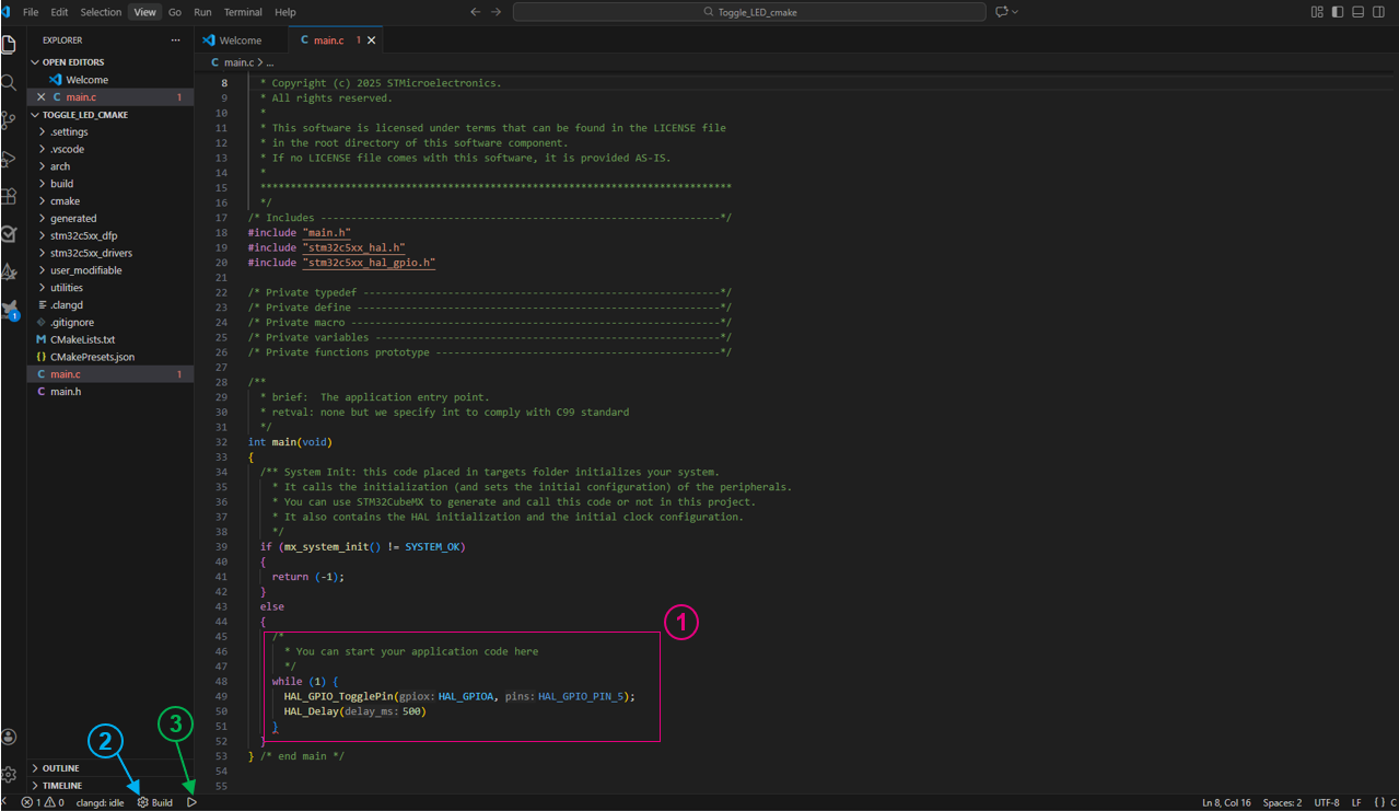
main.c file 
I²C example 
Project creation 
create a project by following the steps described in Create a project from a board and Project setup.
For this demonstration, pinout and clock configurations remain as default.
I²C activation 
Open the peripheral view (1): Click its icon from the left bar.
Extend connectivity section (2).
Enable I²C1 (3): Locate I²C1 and change its status from Disabled to I²C by selecting the option from the dropdown menu.
Note
Refer to Peripherals for more details on how to activate peripherals.
Note
The system displays a notification indicating that the peripheral I2C1 signals are assigned to specific pins.
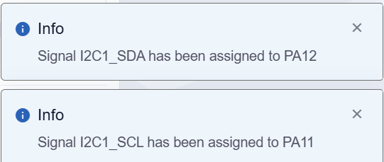
I²C configuration 
Once enabled, the user can open the software configuration following these steps:
Open the I²C1 Settings (1).
Update the resources allocation (2): Change the default assignment if needed.
Update the configuration (3): Expend the different sections to list all available parameters.
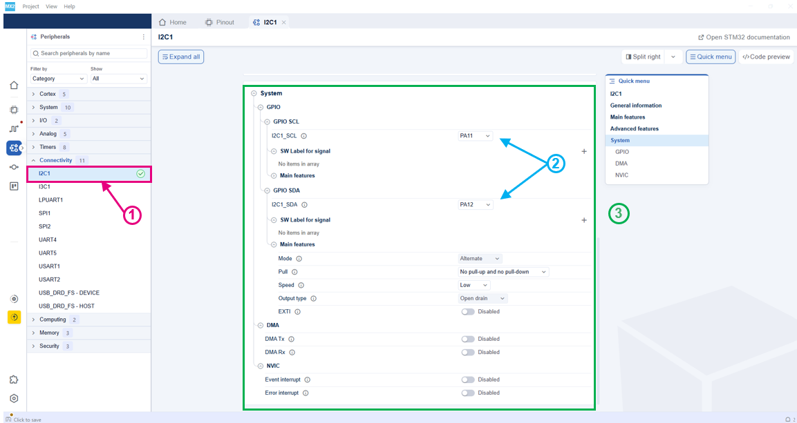
Access I²C configuration 
Enable event interruption and error detection (4): Extend the system section to get the list of interruptions.
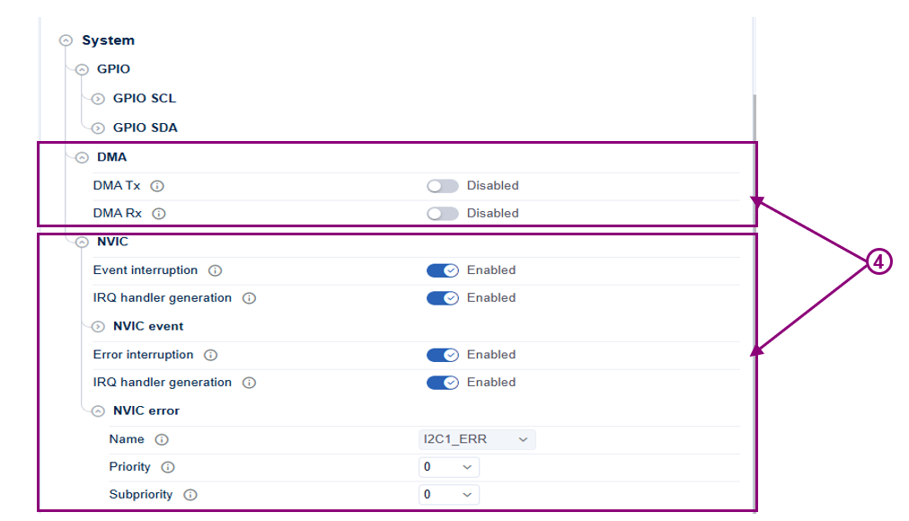
Enable I²C2 event and error interrupts 
The priority level can be modified either from the I²C configuration or from the NVIC view.
Note
The NVIC view can be accessed from the Peripheral View under the System category.
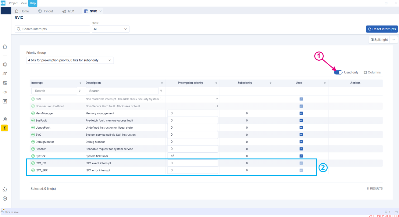
I²C2 interrupts in NVIC view 
IDE project generation 
Apply the same steps described in the IDE project generation section from LED toggle example.