
 USBX
How to write a USBX low-level interface 
This page describes the structure of the STM32 USBX low-level interface and the expected behavior of the STM32 controller adapters used by USBX.
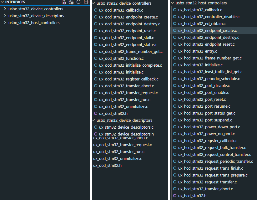
The low-level middleware entry point files. 
STM32CubeMX view of the low-level binding 
In STM32CubeMX, the low-level USBX interface is not configured as a single code block. It is derived from the controller role, the enabled USB classes, and the selected USB peripheral instances.
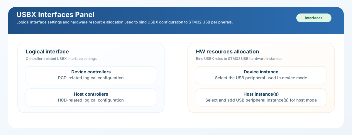
STM32CubeMX interfaces panel used to bind USBX device or host roles to the STM32 controller instances. 
In practice, STM32CubeMX decides the low-level integration path through three questions:
-
does the project use the device controller path, the host controller path, or both
-
which STM32 USB peripheral instance is bound to each active role
-
which generated USBX files must connect the middleware stack to the STM32 HAL
What STM32CubeMX generates for low-level integration 
For low-level integration, the generated project typically gives you:
-
- the USBX application wrapper that calls the selected device-side or host-side
-
startup path
-
- the role-specific USBX source files that bind the stack to the enabled roles
-
when the corresponding generation conditions are satisfied
-
- class-specific support files that expect the controller role and endpoint
-
plan selected in CubeMX
What still remains under user control:
-
HAL clock, GPIO, PHY, VBUS, and board-routing configuration
-
cache, DMA, and buffer-alignment policy
-
descriptor coherence for device mode
-
the final application callbacks attached to the enabled USB classes
Required dependencies:
-
-
device low-level binding requires HAL
PCDsupport and a USB peripheral -
configured in device mode
-
device low-level binding requires HAL
-
-
host low-level binding requires HAL
HCDsupport and a USB peripheral -
configured in host mode
-
host low-level binding requires HAL
-
each active role must also have at least one matching USB class enabled
Low-level screenshots explained 
The following screenshots show how the low-level binding is expressed in the STM32CubeMX UI.
-
start here after the execution mode and class mix are already known. This is the top-level bridge between USBX roles, controller settings, and hardware allocation, so it should reflect the real board design rather than be used to guess it.
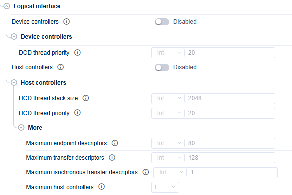
Logical-interface close-up showing the role-enable decisions. 
-
enable device controllers only when the STM32 must act as a USB device, and enable host controllers only when it must enumerate external USB peripherals. Turn on both only for a real dual-role design.

Device-controller detail view used to tune DCD-side behavior. 
-
keep
              DCD


              thread


              priority
high enough to serve endpoint activity before upper USBX work. In practice it should stay aligned with, or above, the enumeration and class thread priorities.
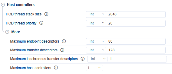
Host-controller detail view used to tune HCD-side behavior. 
-
tune
HCD thread stack size,HCD thread priority, and the advanced host limits only when the real topology needs them. The defaults are usually enough for a simple host design.
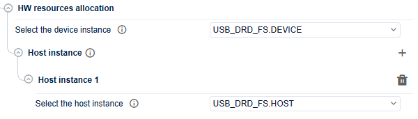
Resource-allocation close-up showing device and host USB instance binding. 
-
bind each USBX role to a USB peripheral that is already configured with the matching STM32 mode. Device-role binding must use a DEVICE-mode instance, and host-role binding must use a HOST-mode instance.
-
confirm that the USBX middleware is active before debugging any low-level binding issue. If it is disabled here, the role and resource-allocation panels cannot produce valid generated code.
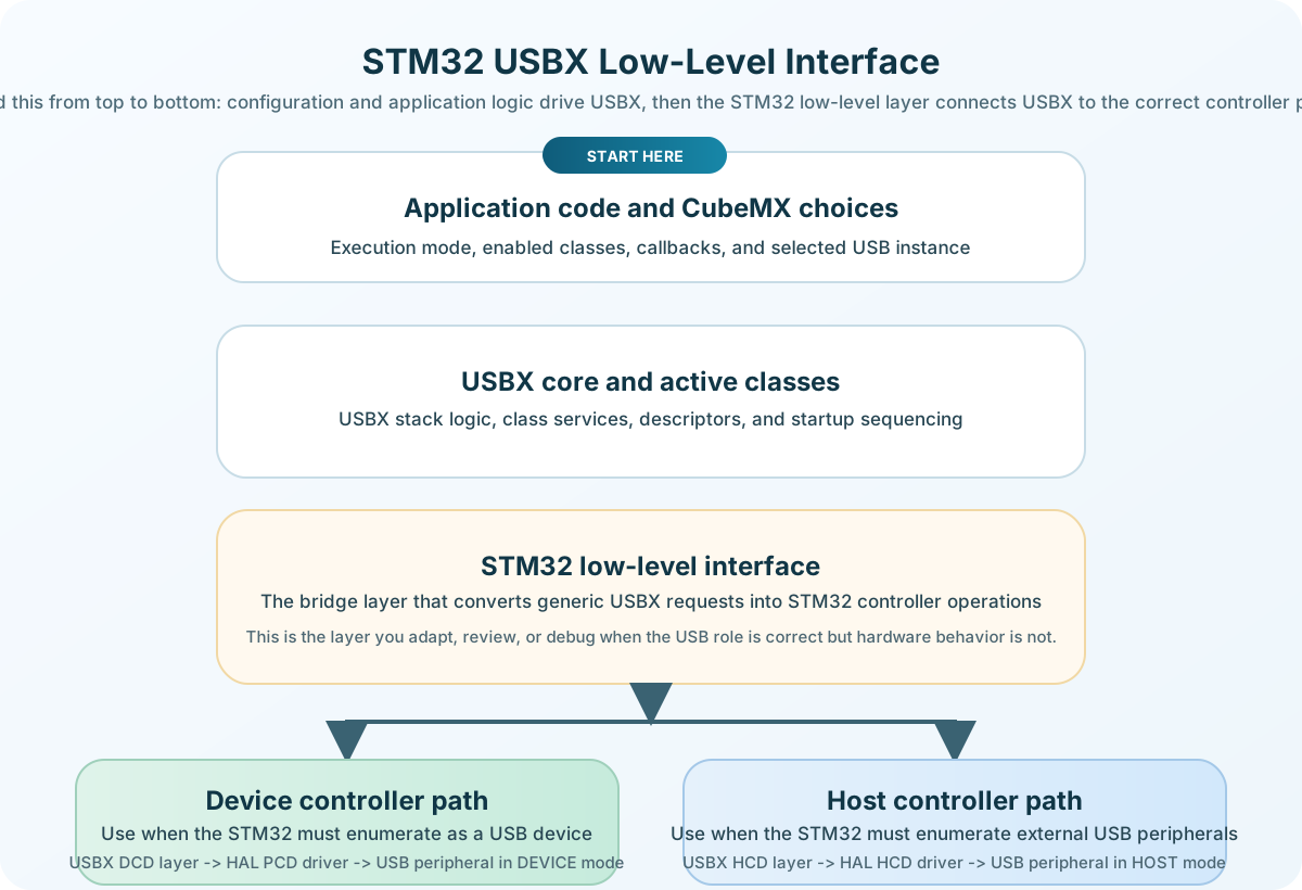
Diagram showing how the STM32 low-level interface connects the USBX stack to the device-controller or host-controller path. 
-
use the diagram to verify the architecture, not to set parameters. If the low-level integration does not match the intended role or peripheral, the mismatch usually starts with role enablement or instance binding.
Low-level interface structure 
In the STM32 USBX middleware, the low-level integration is split across three main folders:
-
interfaces/usbx_stm32_device_controllersfor the STM32 device controller -
interfaces/usbx_stm32_host_controllersfor the STM32 host controller -
-
interfaces/usbx_stm32_device_descriptorsfor the STM32 reference device -
descriptor generator
-
These layers sit between the generic USBX stack and the STM32 HAL PCD or HCD drivers.
- Practical review point:
-
when low-level integration fails, first verify the selected role, the bound USB instance, and the matching HAL peripheral mode. Most low-level failures start with an inconsistent role-to-instance configuration rather than with the controller driver itself.
Device-side low-level interface 
For device mode, the main STM32 bridge is the DCD layer from
usbx_stm32_device_controllers
.
The device-side entry point uses the STM32 DCD initialization prototype:
UINT ux_dcd_stm32_initialize(ULONG dcd_io, ULONG parameter);
The device controller layer then dispatches USBX device requests through helper functions such as:
-
endpoint create and destroy
-
endpoint reset and stall
-
endpoint status queries
-
transfer request or standalone transfer run
-
controller initialization and uninitialization
This folder also provides the HAL callback bridge for:
-
setup stage
-
IN and OUT transfer completion
-
reset
-
connect and disconnect
-
suspend and resume
-
start-of-frame notifications
-
LPM and BCD events
In practice, the device-side low-level interface must coordinate:
-
USBX device requests
-
STM32 HAL PCD operations
-
endpoint state tracking
-
descriptor content and class callback sequencing
Host-side low-level interface 
For host mode, the main STM32 bridge is the HCD layer from
usbx_stm32_host_controllers
.
The host-side entry point uses the STM32 HCD initialization prototype:
UINT ux_hcd_stm32_initialize(UX_HCD *hcd);
The host controller layer then handles operations such as:
-
controller enable and disable
-
endpoint create, destroy, and reset
-
bulk, control, and periodic transfer requests
-
port enable, disable, suspend, resume, and reset
-
frame-number queries
-
transfer abort and transfer completion handling
-
periodic scheduling and channel allocation
The STM32 host bridge also receives HAL notifications for:
-
SOF events
-
port connect and disconnect
-
port enabled and disabled transitions
-
suspend and resume
-
URB state changes
Descriptor layer 
For device mode, the descriptor content is a separate concern from the STM32
controller driver itself. The reference STM32 implementation is stored in
interfaces/usbx_stm32_device_descriptors
and is used to build the device,
configuration, string, and language descriptor content exposed to
ux_device_stack_initialize()
.
If the default descriptor generator is not enough, the project can replace this layer with its own descriptor source as long as the framework arrays remain consistent with the enabled device classes and endpoint plan.
This means the low-level interface is only correct when three views remain coherent at the same time: the CubeMX role selection, the generated USBX startup code, and the final device descriptor layout.
Buffer ownership and parameters 
The low-level interface must define, at minimum:
-
which layer owns each transfer buffer
-
-
how endpoint buffers are allocated when
UX_DEVICE_ENDPOINT_BUFFER_OWNERis -
configured for core-managed or class-managed buffers
-
how endpoint buffers are allocated when
-
whether cache maintenance is required on DMA-capable systems
-
how alignment constraints are handled for USB data buffers
-
how HAL return codes and controller events are mapped to USBX status values
For device mode, the main data structures are centered on
UX_DCD_STM32
,
UX_DCD_STM32_ED
,
UX_SLAVE_ENDPOINT
, and
UX_SLAVE_TRANSFER
.
For host mode, the main data structures are centered on
UX_HCD_STM32
,
UX_HCD_STM32_ED
,
UX_ENDPOINT
, and
UX_TRANSFER
.
Practical implementation rules 
When adapting or extending the STM32 low-level interface, keep the following rules:
-
- device and host callbacks must forward controller events without losing USBX
-
state coherence
-
- endpoint addresses, packet sizes, and transfer directions must match the
-
descriptors and enabled classes
-
- suspend, resume, and disconnect behavior must be propagated consistently to
-
the middleware
-
cache and DMA rules must be documented and enforced for all transfer buffers
-
- board-specific VBUS, PHY, power, and port-routing code should stay in the
-
board layer, not in the generic USBX controller adaptation
Links 
-
How to configure USBX How to configure USBX
-
USBX STM32Cube integration USBX STM32Cube integration
-
How to port USBX on RTOS How to port USBX on RTOS