
 general

How to deploy your AI model on STM32N6 
This tutorial details the steps to generate an AI application running on a STM32N6 microcontroller, embedding the ST Neural-ART™ Accelerator Neural Processing Unit (NPU). It uses the STM32N6570-DK as the reference board.
Objective 
Generate a working AI inference application for the STM32N6570-DK by converting your AI model into C-code with STM32Cube AI Studio, configuring board peripherals and generating firmware project in STM32CubeMX, integrating model files and flashing the board.
Important
For a fast model evaluation on your board, STM32Cube AI Studio can directly generate a complete firmware project, ready to build and flash. Steps described in Parts 2 and 3 of this tutorial aim to detail required project configurations to implement in your own application.
This tutorial uses Execute in Place (XIP) mode: the external NOR flash is mapped directly into the CPU address space via the XSPI memory-mapped interface. In XIP mode, the FSBL is used to initialize the memory interfaces, the application being fetched from the external flash.
Summary 
Part 1 — Generate AI model C-code with STM32Cube AI Studio
Getting the model
Create a project in STM32Cube AI Studio
Generate AI model code in STM32Cube AI Studio
Part 2 — Create the base firmware project with STM32CubeMX
Create a project from the STM32N6570-DK board selector
Configure System Core: CACHEAXI, CORTEX_M55_S, RCC
Configure Connectivity: USART1, XSPIM, XSPI1, XSPI2
Configure Security: RIF (Application context + NPU Privilege)
Configure Middleware: EXTMEM_MANAGER
Configure Clock
Configure Project Manager: FSBL + Appli structure, STM32CubeIDE, linker settings
Generate code and open the firmware project
Part 3 — Deploy AI model in firmware project with STM32CubeIDE
Copy AI files to the firmware project
Configure the Appli project settings: preprocessor defines, include paths, link library
Edit the linker script
Edit
Appli/main.c: add AI init and process callsAdd BSP libraries from the STM32CubeN6 package
Edit
FSBL/main.c: add BSP memory initializationFlash and run
0. Prerequisites 
Component
Minimum version
Purpose
6.17.0
Project configuration and code generation
1.3.0
STM32N6 MCU package (BSP, HAL drivers)
2.0.0
IDE and compiler
1.2.0
AI model validation and C code generation
2.22.0
Board flashing
4.0.0
AI model validation and C code generation (core component)
You also need an STM32N6570-DK board with a USB Type-C® cable.
Part 1 — Generate AI model C-code with STM32Cube AI Studio 
1. Getting the model 
For this tutorial, we will download a compact image classification model in
.tfliteformat from the STM32 Model Zoo. The STM32 Model Zoo is an open-source repository of pre-trained, STM32-optimized AI models for various applications including predictive maintenance, audio, and more. Each model comes with training scripts and configuration files.The chosen model, a MobileNetV2 α=0.35 — 128×128 INT8, is a lightweight convolutional neural network pre-trained on ImageNet and post-training quantized to INT8 for efficient deployment on AI-accelerated STM32.
Download it from the STM32 Model Zoo: mobilenetv2_a035_128_int8.tflite
2. Create a project in STM32Cube AI Studio 
At this step, we will create an STM32Cube AI Studio project to convert our
.tflitemodel to C code.STM32Cube AI Studio converts your model (
.tfliteor.onnx) into C code optimized for the STM32N6 Neural-ART NPU. The Application variant produces not only the raw network files but also the middlewares and the application source code to run the model.
Open STM32Cube AI Studio.
Create a new project clicking + Project on the top right.
Select From Scratch project creation option.
Set a name for your project (
Test_CubeAIStudio_Mobilenet_050526in this tutorial). Click Next.Set the target development board: STM32N6570-DK. Click Next.
Select the toolchain you will use for building your AI project. For this tutorial, select STM32CubeIDE. Click Create Project. Your STM32Cube AI project is now created:
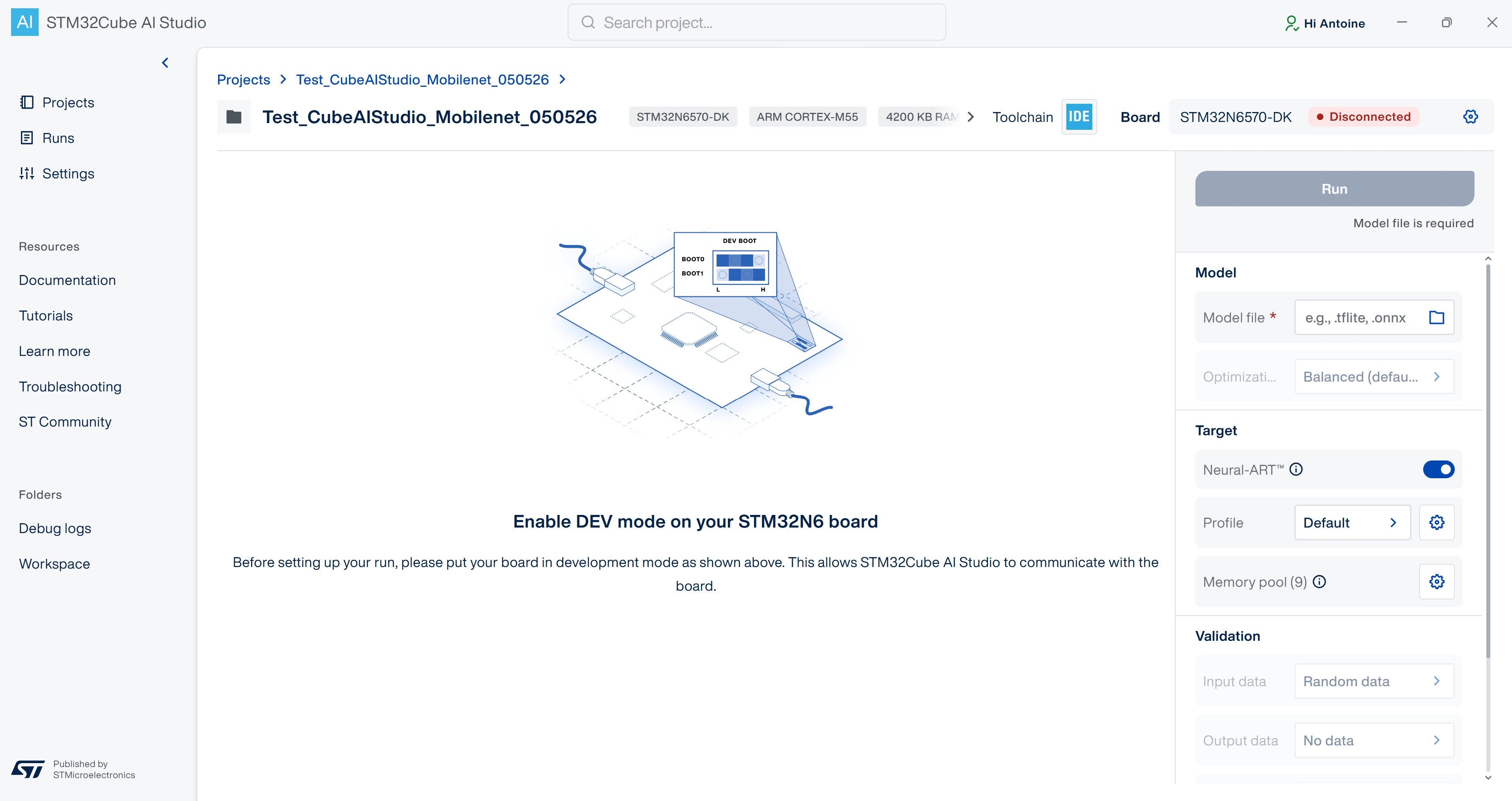
3. Generate AI model code in STM32Cube AI Studio 
On the right bar in Model section, click Model file field to select your model (
mobilenetv2_a035_128_int8.tflite).You will now validate your model to check its compatibility for C-code conversion and memory size. For this, click Run:
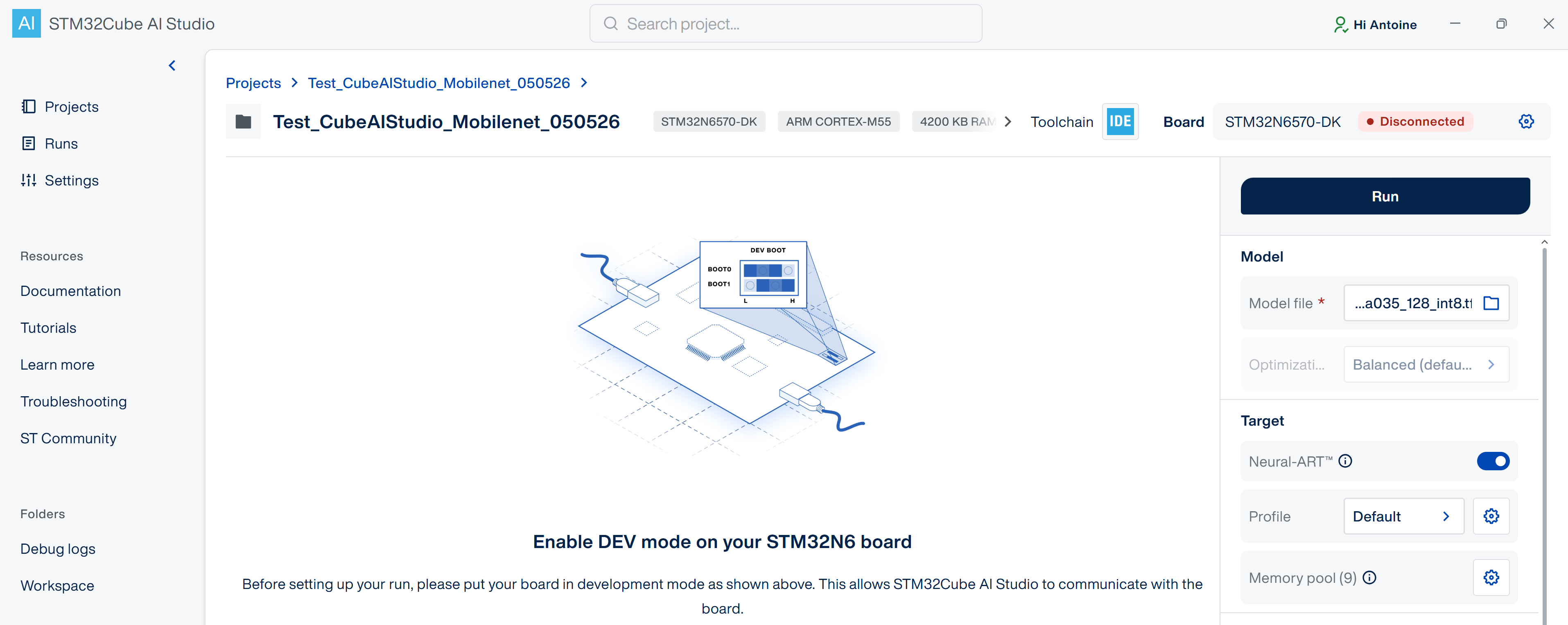
When the validation is successful, click the gear icon on the top right to open Board settings. Check the default settings. The UART interface will be used to set the communication between the board and the host PC. Then, click Save.
UART interface:
USART1Baudrate:
115200RX pin:
PE6TX pin:
PE5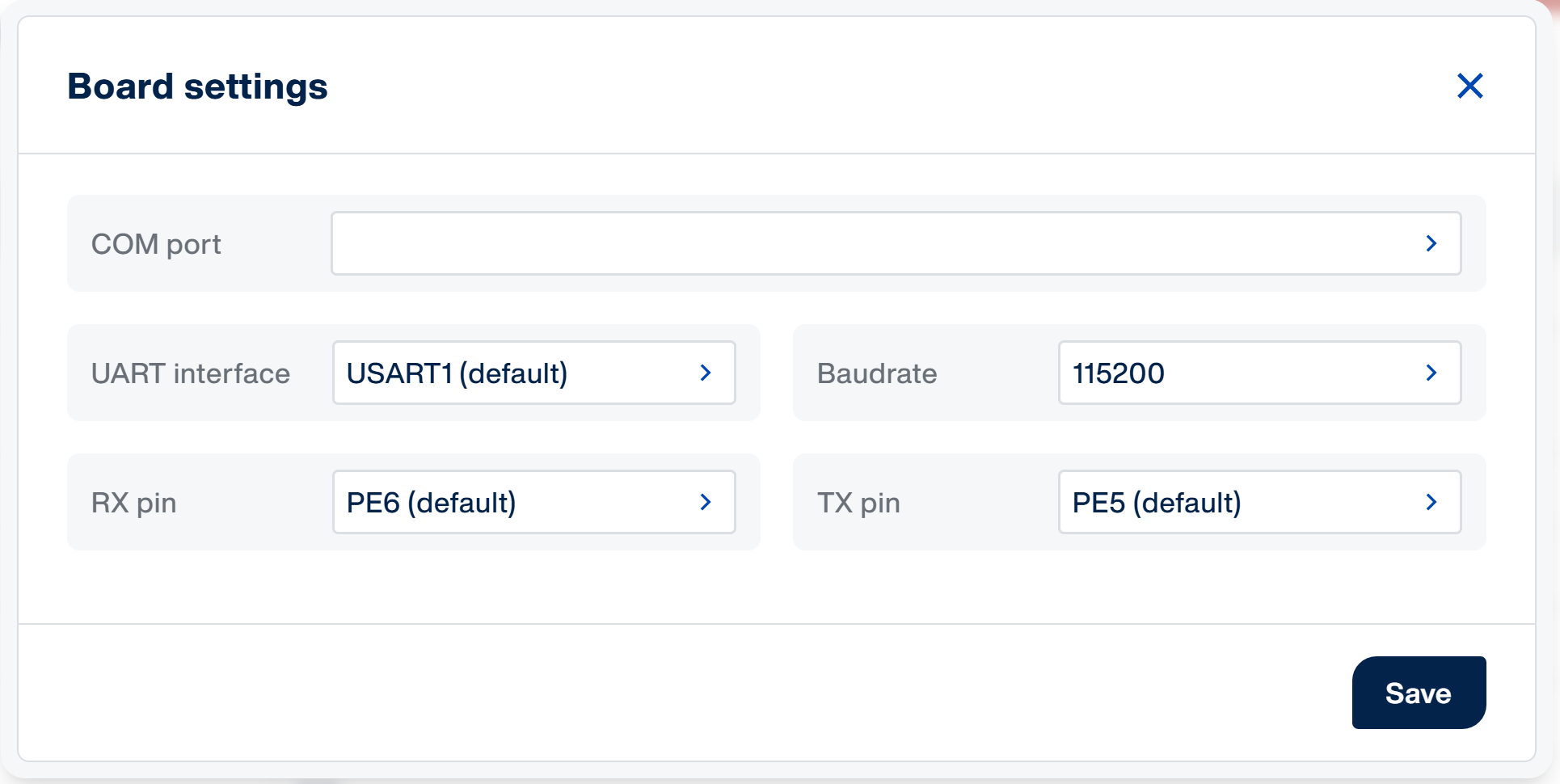
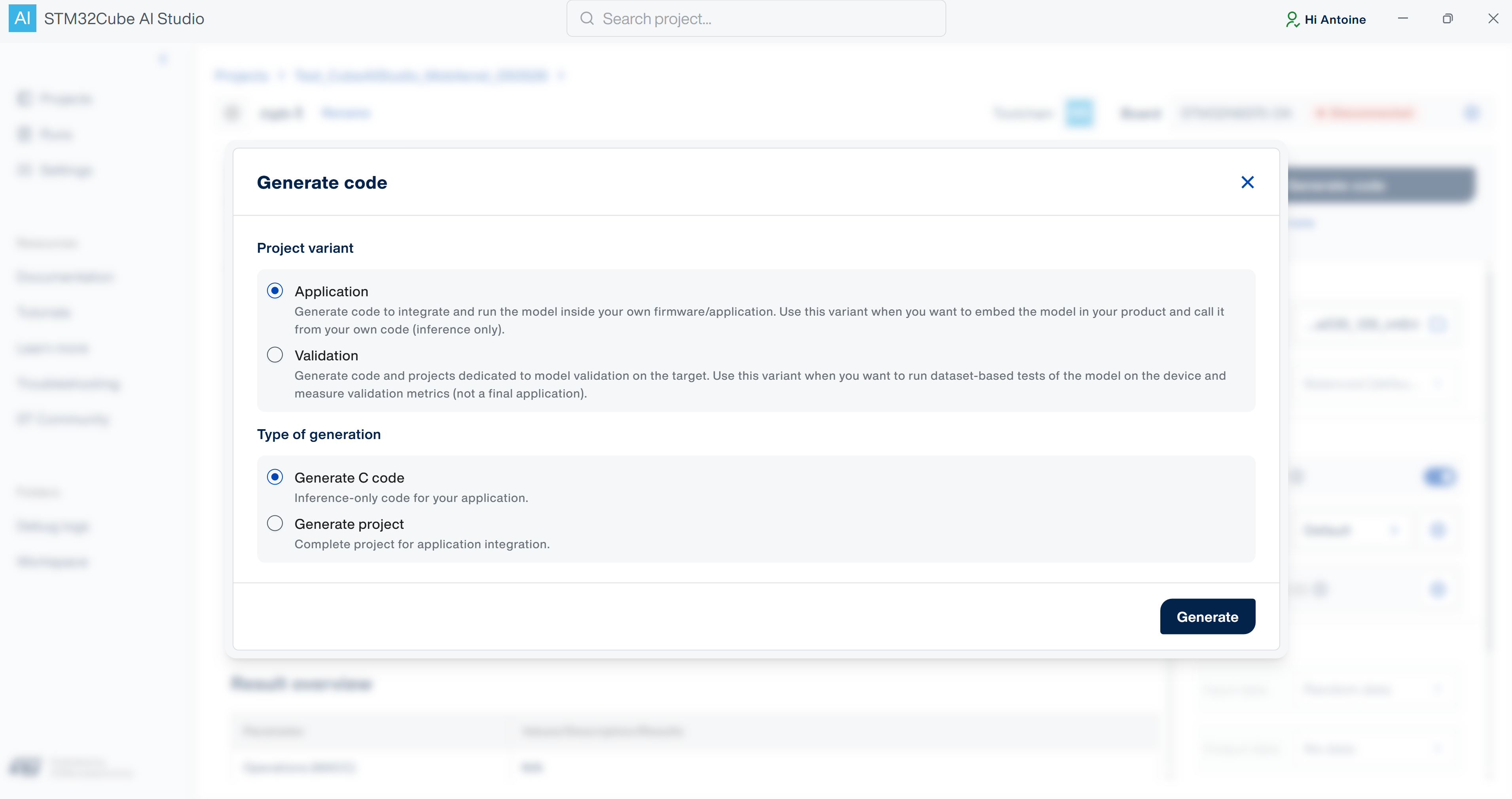
Generate model C-code by clicking Generate code:

Select the Application variant, keep Generate C code, then click Generate. On top of the AI part, the Application variant adds a top level code running an inference each 5 seconds and outputting its execution time.
After the generation, click Download your C model. A .zip archive (named
Test_CubeAIStudio_Mobilenet_050526-run-1-model-network-ApplicationTemplate-code.zipin this tutorial) is produced containing C-code model files and dependencies. Model integration in firmware project will be done in Part 3 of this tutorial.
Part 2 — Create the base firmware project with STM32CubeMX 
In this part we will use STM32CubeMX to initialize board peripherals and generate the firmware project for STM32CubeIDE.
A ready-to-use .ioc file with all the settings described below is available for download. You can use it directly in STM32CubeMX instead of configuring the project from scratch. All the steps of this Part 2 are nonetheless detailed below so you can understand how to proceed by yourself and adapt the configuration to your own application.
1. Create a project from the STM32N6570-DK board selector 
Starting from the board selector pre-fills all board-specific hardware and software settings allowing to run your AI application. Only the needed peripherals will be enabled.
Open STM32CubeMX and click Access to Board Selector.
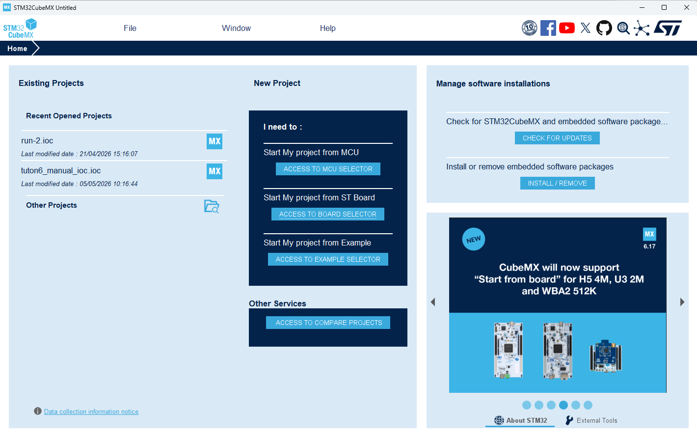
In the Commercial Part Number field, enter STM32N6570-DK. Select the item in the Board List.
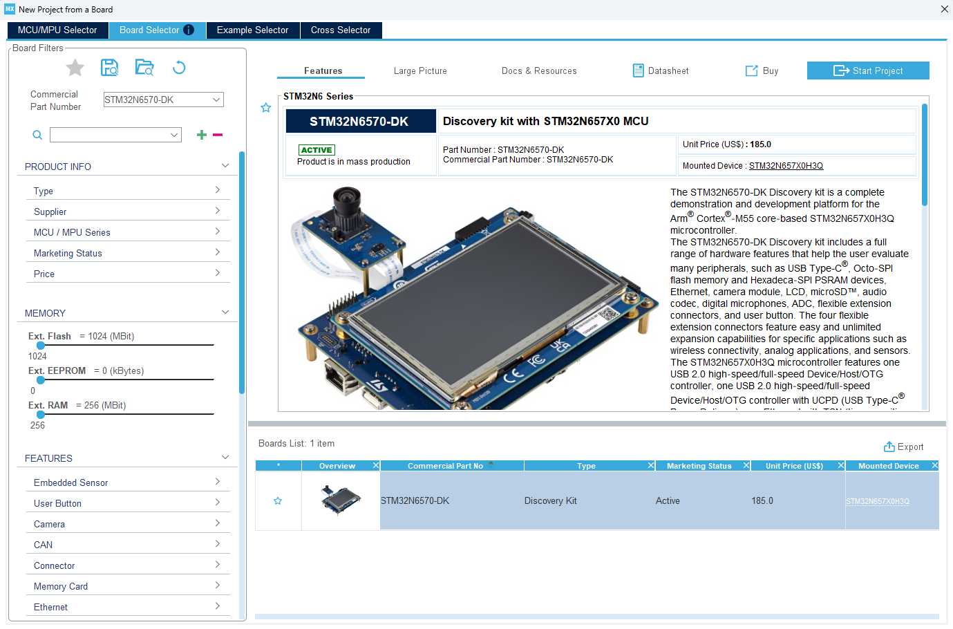
Click Start Project.
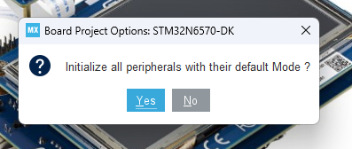
When asked to initialize all peripherals with their default mode, click No.
Note
Declining auto-initialization is important: the board template enables many peripherals by default that are not needed here and would create pin conflicts.
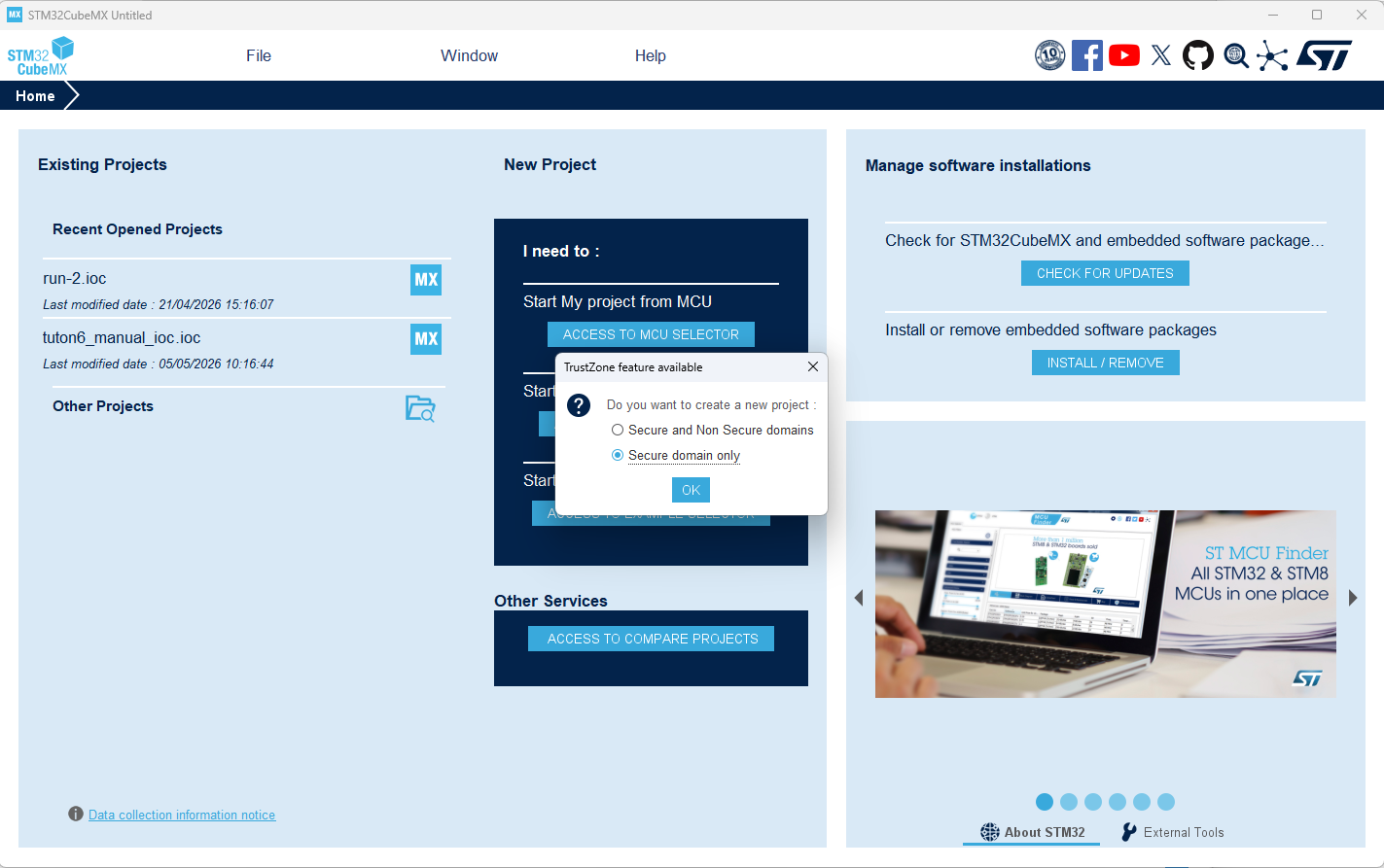
When asked for the TrustZone feature, select Secure domain only and click OK.
Note
The choice of “Secure domain only” option is for a simplicity purpose of the generated project structure, since we do not need to separate application from secure assets.
2. Configure System Core: CACHEAXI, CORTEX_M55_S, RCC 
CACHEAXI:
The AXI interconnect cache (CACHEAXI) improves memory-access performance for the CPU and NPU when they transfer data through external memory. It must be enabled for the Application context so it is active when inference runs.
In System Core, select CACHEAXI.
Enable the Application runtime context.
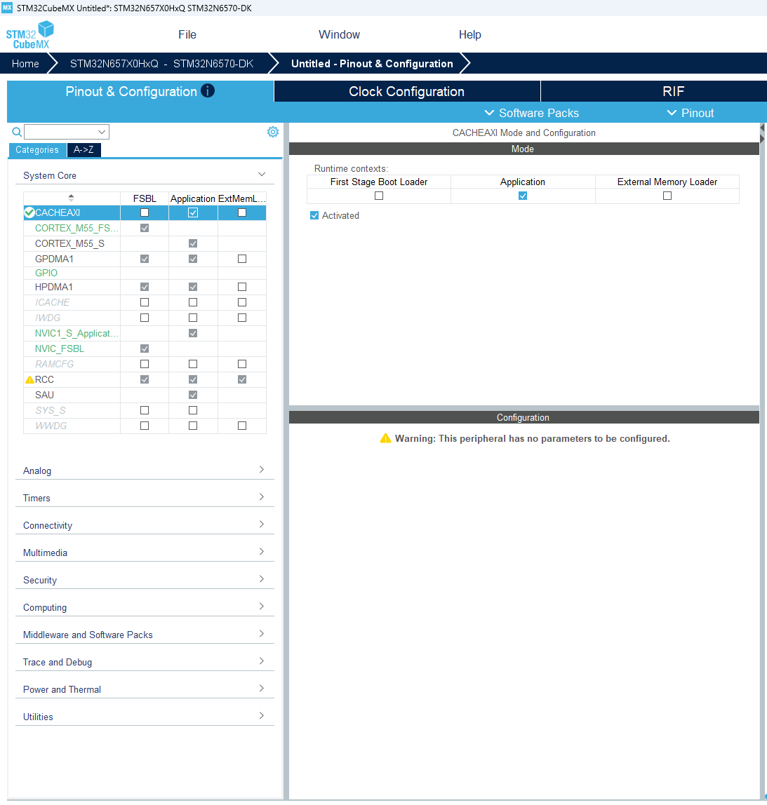
CORTEX_M55_S:
The Cortex-M55 instruction cache (I-cache) and data cache (D-cache) drastically reduce latency when the CPU fetches code and data from external flash in memory-mapped mode.
In System Core, select CORTEX_M55_S.
In Parameter Settings → Cortex Interface Settings, enable CPU ICACHE and CPU DCACHE.
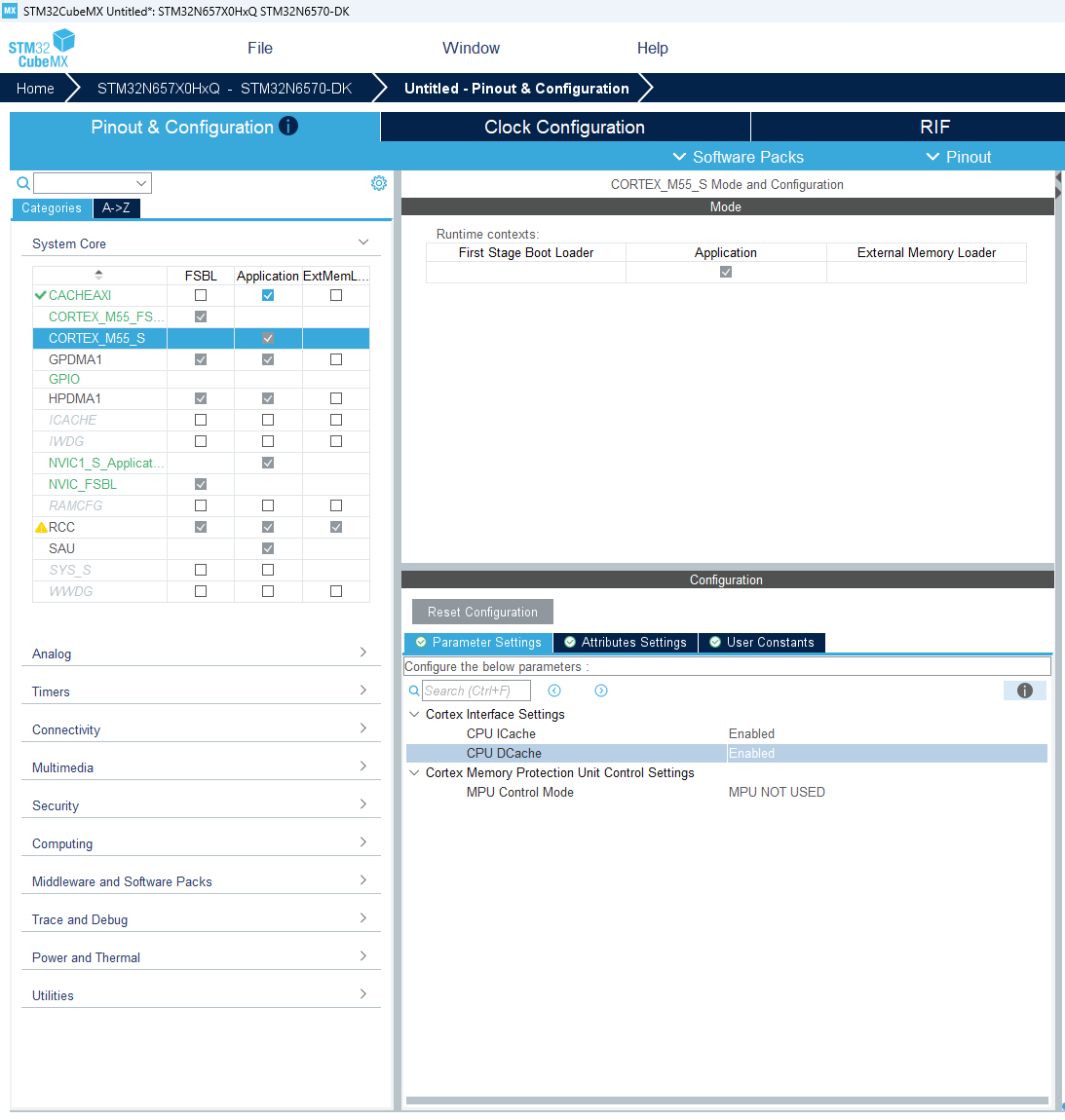
RCC:
The Reset and Clock Control (RCC) manages the system clocks and power settings. To maximize STM32N6 performance for AI model execution, the Power Regulator Voltage Scale may be adjusted.
In System Core, select RCC.
In Parameter Settings → Power Parameters, set the Power Regulator Voltage Scale to Power Regulator Voltage Scale 0.
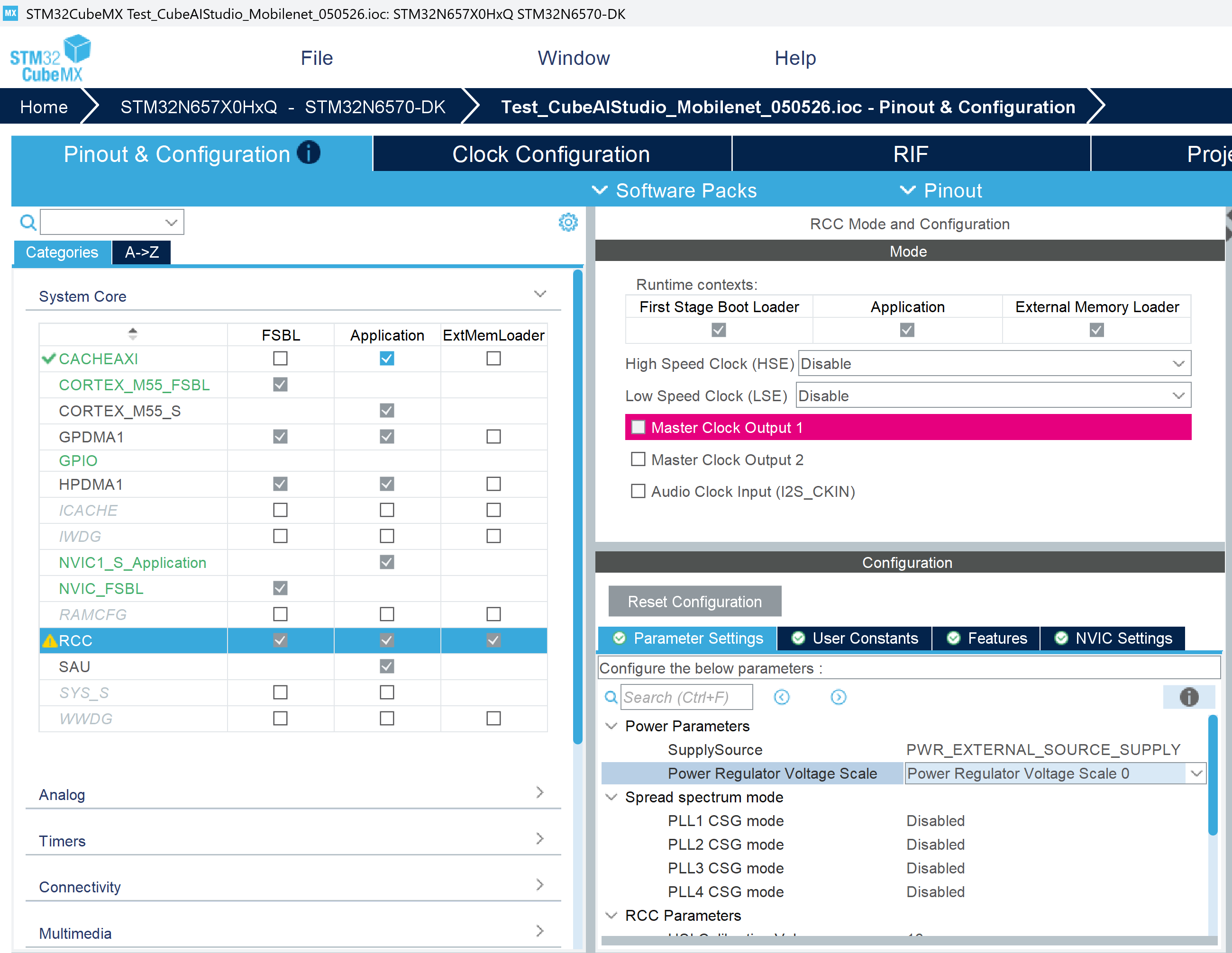
3. Configure Connectivity: USART1, XSPIM, XSPI1, XSPI2 
USART1:
USART1 is used to print inference results to a serial terminal through Virtual COM Port (115200 bauds).
In Connectivity, select USART1.
Disable the First Stage Boot Loader runtime context.
Enable the Application runtime context.
Set the mode as Asynchronous.
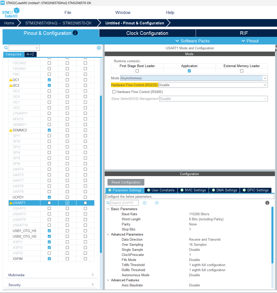
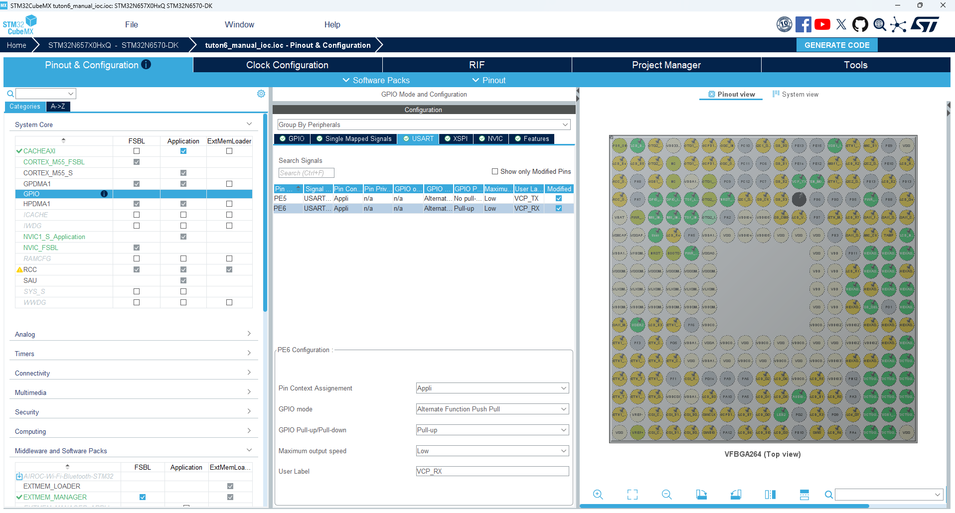
For a correct USART1 idle-line detection on the STM32N6570-DK, VCP_RX pin (PE6) requires a pull-up. In System Core, select GPIO and switch to the USART tab.
Select PE6 and set GPIO Pull-up/Pull-down to Pull-up.
XSPIM:
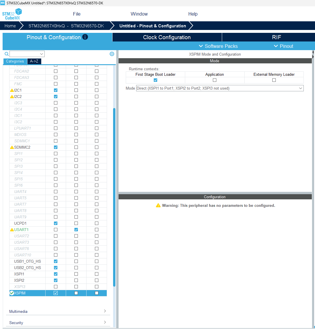
The XSPI Manager (XSPIM) is the multiplexer that routes the two XSPI interfaces (XSPI1, XSPI2) to the physical memory ports. It must be configured in the FSBL context so the boot loader can set up memory-mapped access before jumping to the application.
Back to Connectivity, select XSPIM.
Enable the First Stage Boot Loader runtime context.
Set this peripheral mode as Direct (XSPI1 on Port1, XSPI2 on Port 2, XSPI3 not used).
XSPI1:
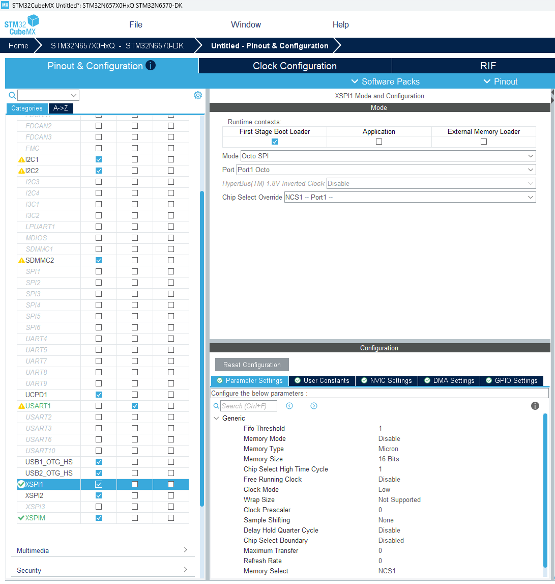
XSPI1 is connected to the external HyperRAM (PSRAM) on the STM32N6570-DK. For a big model, the NPU uses this RAM as its activation buffer at inference time.
Note
Configuring XSPI1 is optional for this tutorial: the MobileNetV2 model used here is small enough to fit entirely in internal RAM, so the NPU does not need the external HyperRAM as activation buffer. This step is kept for completeness, and is required as soon as a bigger model needs more activation buffer memory than the available internal RAM.
Still in Connectivity section, select XSPI1.
Enable the First Stage Boot Loader runtime context.
Set the Mode to Octo SPI.
Set the Port to Port1 Octo
Set the Chip Select Override to NCS1 – Port 1 –.
XSPI2:
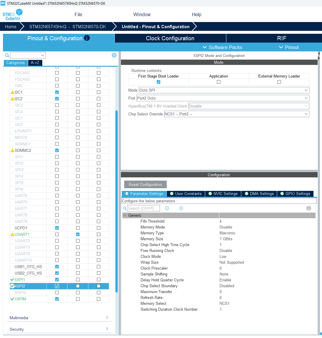
XSPI2 is connected to the external NOR flash, where the application binary and AI model weights are stored. The FSBL maps this flash into the CPU address space (memory-mapped mode) so the application code executes directly from it (XIP) after copy to SRAM.
Still in Connectivity section, select XSPI2.
Enable the First Stage Boot Loader runtime context.
Set the Mode to Octo SPI.
Set the Port to Port2 Octo
Set the Chip Select Override to NCS1 – Port 2 –.
Under Configuration → Parameter Settings, set:
Parameter
Value
Fifo Threshold
4
Memory Type
Macronix
Memory Size
1 GBits
Delay Hold Quarter Cycle
Enable
4. Configure Security: RIF (Application context + NPU Privilege) 
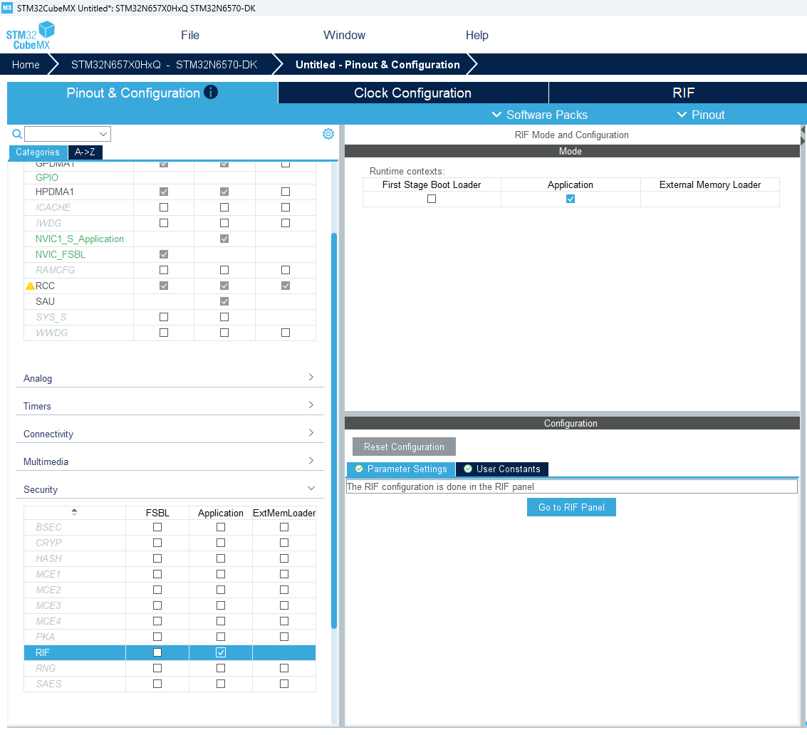
The Resource Isolation Framework (RIF) is STM32N6’s hardware firewall: it controls which bus master (CPU, DMA, NPU) can access which peripheral or memory region. The NPU Privilege flag is mandatory to allow the Neural-ART NPU access to its internal registers.
In Security, select RIF.
Enable the Application runtime context.
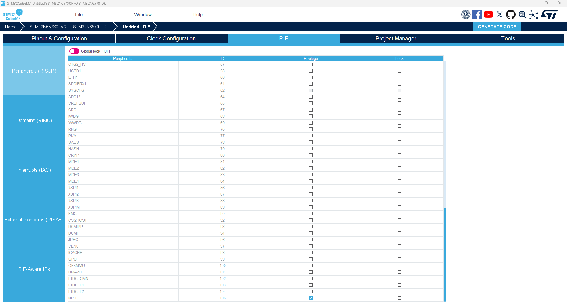
Switch to the RIF tab and check NPU Privilege.
5. Configure Middleware: EXTMEM_MANAGER 
The External Memory Manager (EXTMEM_MANAGER) middleware provides the FSBL with a simple API to copy the Appli binary from NOR flash into SRAM.
Switch back to Pinout & Configuration tab. In Middleware and Software Packs, select EXTMEM_MANAGER.
Enable the First Stage Boot Loader runtime context.
Enable Activate External Memory Manager.
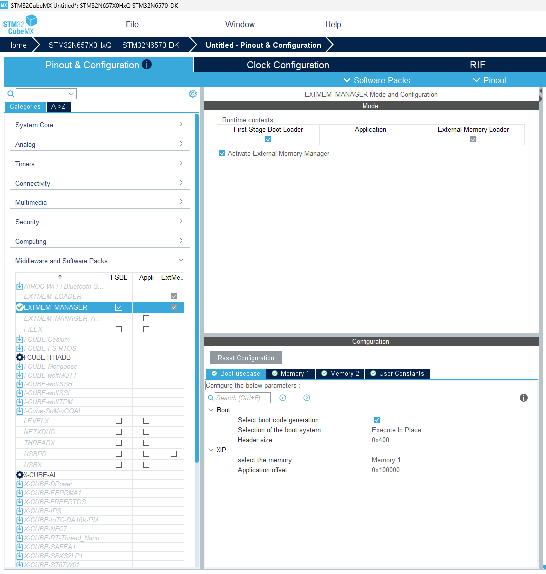
Under Configuration → Boot usecase, enable Select boot code generation.
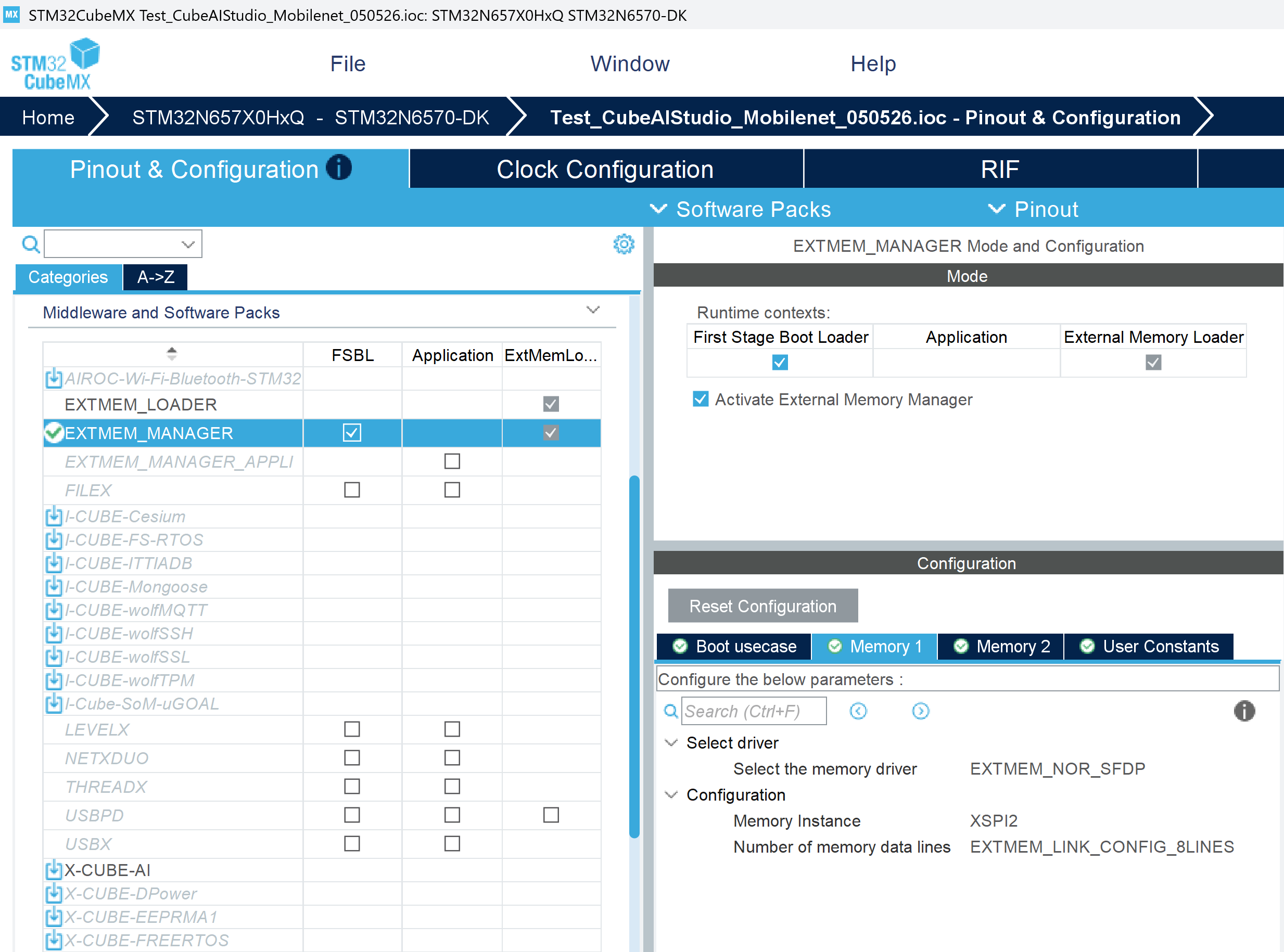
Under Configuration → Memory 1, set Memory Instance to XSPI2 and Number of memory data lines to EXTMEM_LINK_CONFIG_8LINES.
6. Configure Clock 
The clock tree must be configured to run the CPU, AXI bus, and Neural-ART NPU at their target frequencies. The NPU achieves its maximum throughput (and lowest cycles-per-MAC) only at the correct frequency.
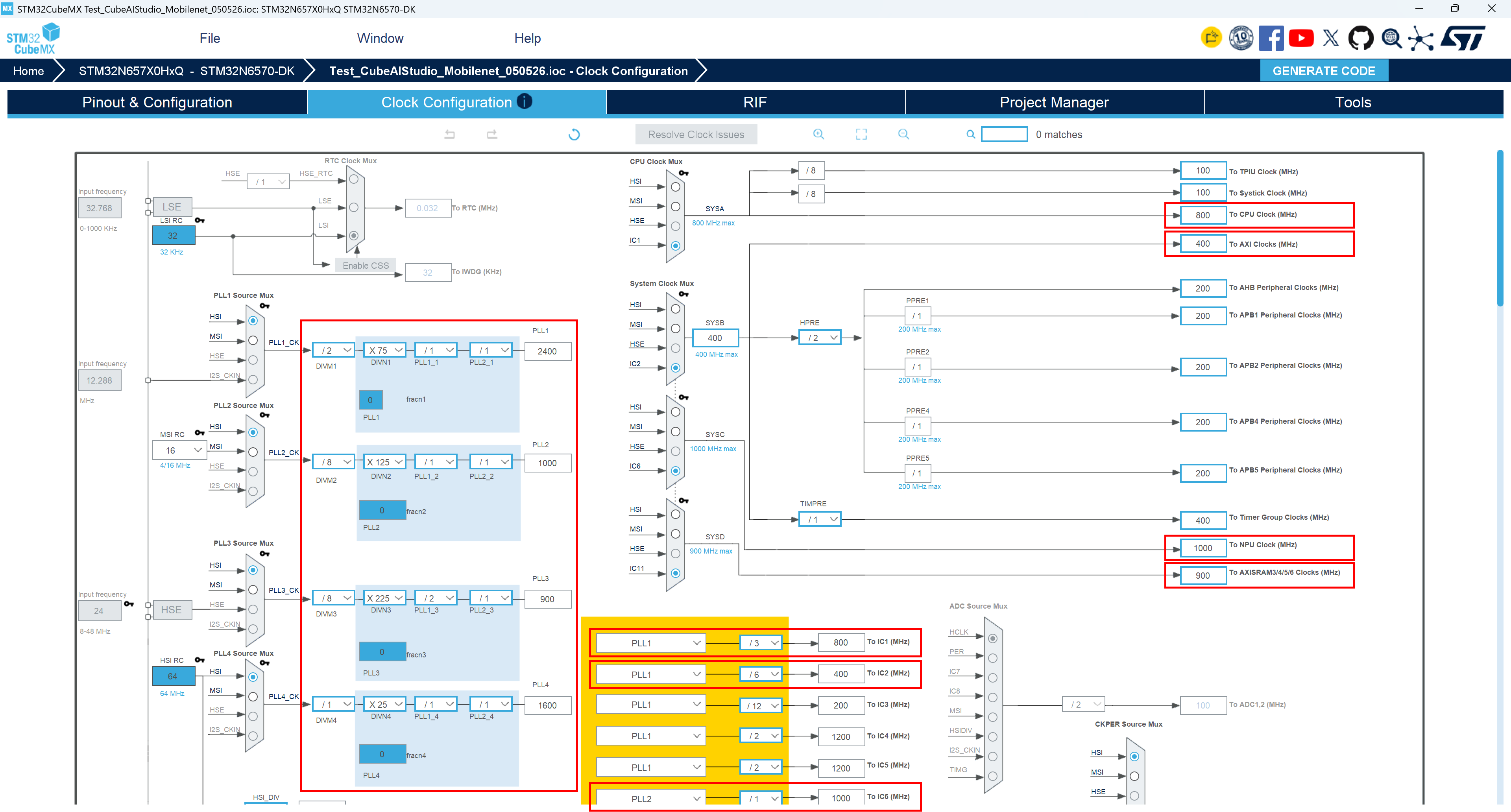
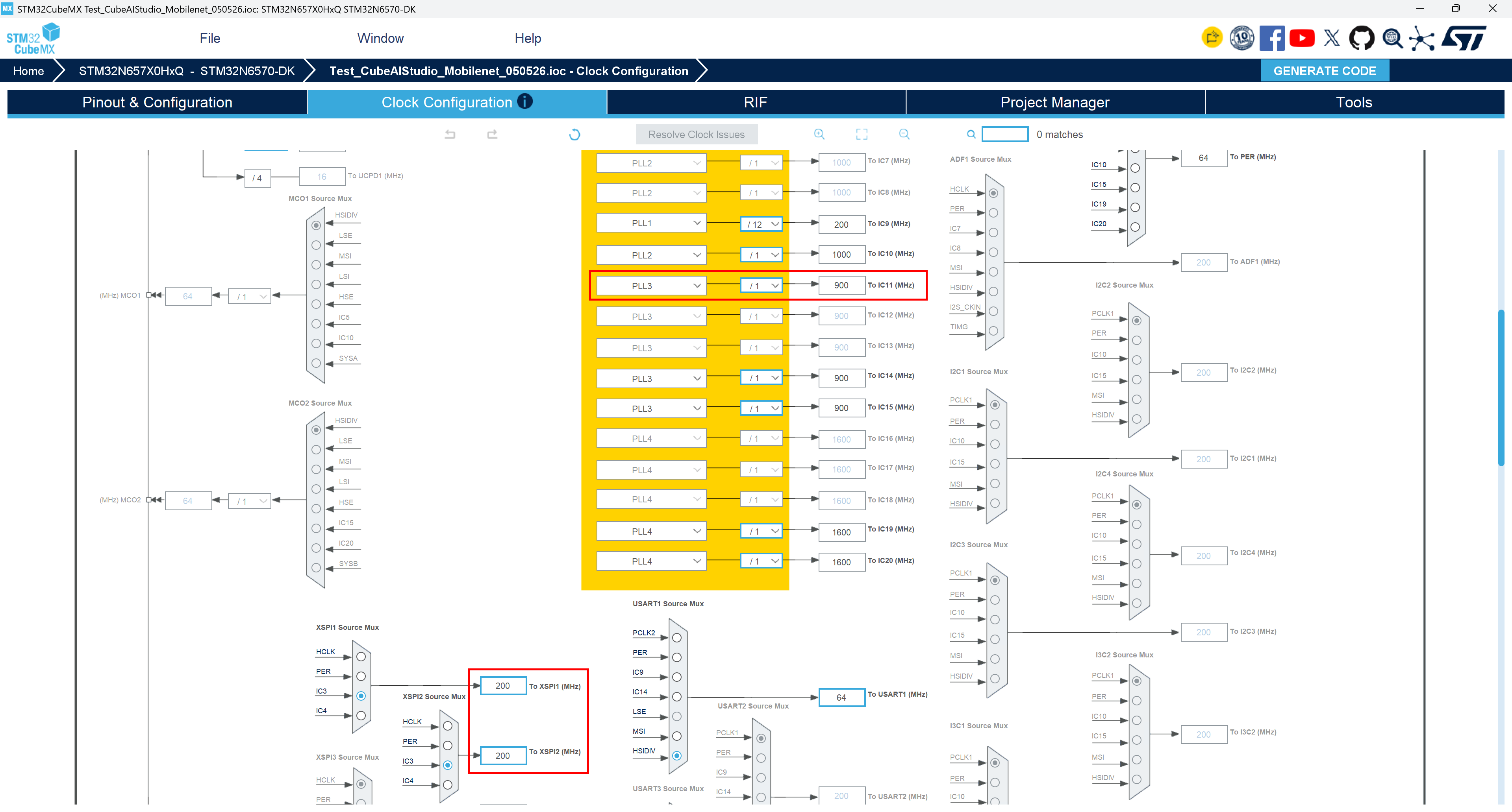
Switch to the Clock Configuration tab and check that following clocks are set at maximum frequency:
CPU Clock = 800 MHz
AXI Clocks = 400 MHz
NPU Clock = 1000 MHz
AXISRAM3/4/5/6 Clocks = 900 MHz
XSPI1 = 200 MHz
XSPI2 = 200 MHz
If not, you should edit some PLL dividers to reach maximum frequencies. For this, you can replicate the settings shown in the two below screenshots:
7. Configure Project Manager: FSBL + Appli structure, STM32CubeIDE, linker settings 
The STM32N6 has no internal flash memory: the boot ROM always loads code from external memory. This requires a two-binary boot architecture — a small FSBL (First Stage Boot Loader) that initializes the system and copies the main Appli binary into SRAM, then jumps to it. STM32CubeMX generates both sub-projects at once from a single
.iocfile.
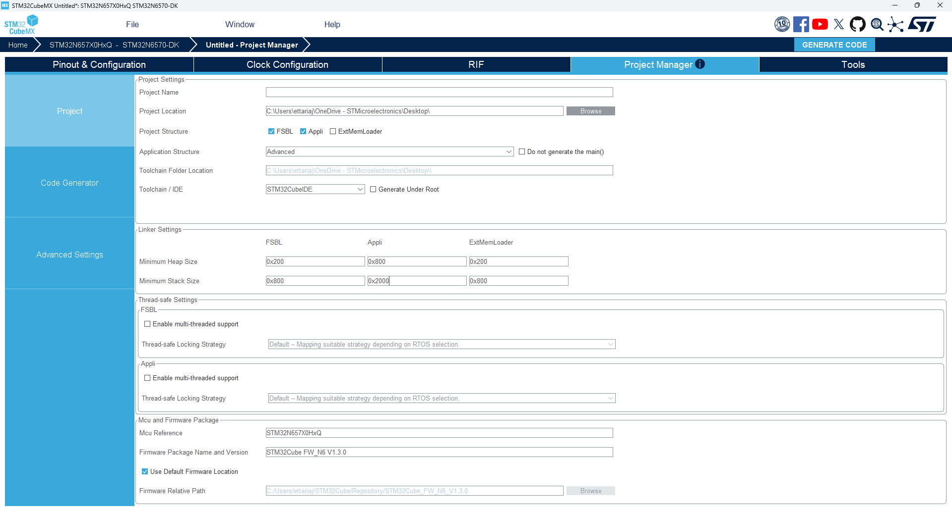
Switch to the Project Manager tab.
Set a Project Name (
Test_CubeAIStudio_Mobilenet_050526in this tutorial).Under Project Structure, select both FSBL and Appli.
Set Toolchain / IDE to STM32CubeIDE and uncheck Generate Under Root.
In Linker Settings, increase Minimum Heap Size for Appli to 0x800 and increase Minimum Stack Size for Appli to 0x2000.
8. Generate code and open the firmware project 
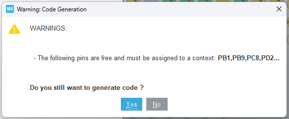
Click Generate Code. In case the following pop-up window appears, click Yes to confirm code generation.
Then, click Open Project in the information window. It imports and opens your firmware project in STM32CubeIDE.
Note
Two sub-projects are imported: Appli (the AI application) and FSBL (First Stage Boot Loader).
Part 3 — Deploy AI model in firmware project with STM32CubeIDE 
In this part, we will integrate the AI model C-code generated in Part 1 into the firmware project generated in Part 2. We will also configure the project settings and edit the main codes to run inferences on the STM32N6570-DK board.
1. Copy AI files to the firmware project 
In your file explorer, unzip the archive generated by STM32Cube AI Studio in Part 1 of this tutorial (named
Test_CubeAIStudio_Mobilenet_050526-run-1-model-network-ApplicationTemplate-code.zip). The folder contains three folders:
ai_generated_network/— low-level model C code (network weights, operator calls)
AI/App/— application-level code (init, process, I/O wrappers)
Middlewares/ST/AI/— AI runtime library (for Neural-ART NPU)In STM32CubeIDE, in the Appli firmware project (named
Test_CubeAIStudio_Mobilenet_050526_Appliin this tutorial):
Under
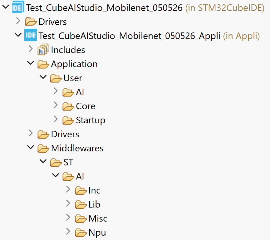
Application/User, create a folder namedAI.In this new AI folder, copy paste .c/.h network files from
Test_CubeAIStudio_Mobilenet_050526-run-1-model-network-ApplicationTemplate-code/ai_generated_network:
network.c
network.h
network_atonbuf.xSPI2.c
network_ecblobs.h
stai_network.c
stai_network.hIn
Application/User/Core, copy paste every files located inTest_CubeAIStudio_Mobilenet_050526-run-1-model-network-ApplicationTemplate-code/AI/App:
app_config.h
app_x-cube-ai.c
app_x-cube-ai.h
bsp_ai.h
network_weights.c
network_weights.h
npu_cache.c
npu_cache.h
npu_init.c
npu_init.h
user_init.c
user_init.hDirectly in
Test_CubeAIStudio_Mobilenet_050526_Appli, copy paste Middlewares folder fromTest_CubeAIStudio_Mobilenet_050526-run-1-model-network-ApplicationTemplate-code.The resulting project tree should look like:
2. Configure the Appli project settings: preprocessor defines, include paths, link library 
You will have to declare preprocessor defines to configure the ATON runtime (the Neural-ART execution engine) and include paths to expose the generated API and runtime headers to the compiler. The runtime library (
NetworkRuntime<version>_CM55_GCC.a) is a pre-compiled static library that implements the NPU scheduling layer; it is not generated from source and must be linked explicitly.Open Appli project properties ( Project → Properties → C/C++ Build → Settings → Tool Settings):
Preprocessor defines (
MCU/MPU GCC Compiler → Preprocessor):HAVE_NETWORK_INFO LL_ATON_DUMP_DEBUG_API LL_ATON_PLATFORM=LL_ATON_PLAT_STM32N6 LL_ATON_OSAL=LL_ATON_OSAL_BARE_METAL LL_ATON_RT_MODE=LL_ATON_RT_ASYNC LL_ATON_SW_FALLBACK LL_ATON_EB_DBG_INFO LL_ATON_DBG_BUFFER_INFO_EXCLUDED=1Include paths (
MCU/MPU GCC Compiler → Include paths):../Application/User/AI ../Application/User/Core ../Middlewares/ST/AI/Inc ../Middlewares/ST/AI/Misc/Inc ../Middlewares/ST/AI/NpuLibraries (
MCU/MPU


               GCC


               Linker


               →


               Libraries
):
Libraries — add:
:NetworkRuntime<version>_CM55_GCC.a, replacing<version>with the actual version number of the library (e.g.:NetworkRuntime1200_CM55_GCC.a)Library search path — add:
../Middlewares/ST/AI/LibThen, click Apply and Close to save the settings.
3. Edit the linker script 
The default linker script generated by STM32CubeMX is written for a standard application. The Neural-ART NPU runtime requires specific internal SRAM banks to be declared. The AI model weights stored in external NOR flash also need a dedicated region.
Still in the Appli project, open
STM32N657X0HXQ_ROMxspi2.ldand apply the two edits below.Edit 1 — Replace the
MEMORYblock:Replace the two-region block:
MEMORY
{
  ROM  (xrw)  : ORIGIN = 0x70100400, LENGTH = 511K
  RAM  (xrw)  : ORIGIN = 0x34000000, LENGTH = 2048K
}
with the following eight-region block:
MEMORY
{
  RAM      (xrw) : ORIGIN = 0x34000000, LENGTH = 0x100000
  AXISRAM2 (xrw) : ORIGIN = 0x34100000, LENGTH = 0x100000
  AXISRAM3 (xrw) : ORIGIN = 0x34200000, LENGTH = 0x70000  /* NPU RAM: section allocated by ST Edge AI Core */
  AXISRAM4 (xrw) : ORIGIN = 0x34270000, LENGTH = 0x70000  /* NPU RAM: section allocated by ST Edge AI Core */
  AXISRAM5 (xrw) : ORIGIN = 0x342e0000, LENGTH = 0x70000  /* NPU RAM: section allocated by ST Edge AI Core */
  AXISRAM6 (xrw) : ORIGIN = 0x34350000, LENGTH = 0x70000  /* NPU RAM: section allocated by ST Edge AI Core */
  ROM      (xrw) : ORIGIN = 0x70100400, LENGTH = 0x7fc00
  EXTFLASH  (rx) : ORIGIN = 0x70180000, LENGTH = 0x7e80000
}
The
RAMregion is now limited to AXISRAM1 (1 MB), which is the main application RAM.AXISRAM3–6are the SRAM banks that the NPU runtime uses as activation buffers.ROMis shortened to the SRAM copy area used for code, whileEXTFLASHcovers the remaining NOR flash address space where the AI model weights are stored.Edit 2 — Add AI output sections at the top of
SECTIONS:Immediately before the
.isr_vectorsection, insert the following eight output sections:/* NPU activation buffers and model weights placed by ST Edge AI Core */ .AI_AXIFLEXMEM (NOLOAD) : { . = ALIGN(4); KEEP(*(.AI_AXIFLEXMEM)) . = ALIGN(4); } >RAM .AI_AXISRAM1 (NOLOAD) : { . = ALIGN(4); KEEP(*(.AI_AXISRAM1)) . = ALIGN(4); } >RAM .AI_AXISRAM2 (NOLOAD) : { . = ALIGN(4); KEEP(*(.AI_AXISRAM2)) . = ALIGN(4); } >AXISRAM2 .AI_AXISRAM3 (NOLOAD) : { . = ALIGN(4); KEEP(*(.AI_AXISRAM3)) . = ALIGN(4); } >AXISRAM3 .AI_AXISRAM4 (NOLOAD) : { . = ALIGN(4); KEEP(*(.AI_AXISRAM4)) . = ALIGN(4); } >AXISRAM4 .AI_AXISRAM5 (NOLOAD) : { . = ALIGN(4); KEEP(*(.AI_AXISRAM5)) . = ALIGN(4); } >AXISRAM5 .AI_AXISRAM6 (NOLOAD) : { . = ALIGN(4); KEEP(*(.AI_AXISRAM6)) . = ALIGN(4); } >AXISRAM6 .AI_XSPI2 : { . = ALIGN(4); KEEP(*(.AI_XSPI2)) *_atonbuf.xSPI2*(.rodata*) . = ALIGN(4); } >EXTFLASHThe
(NOLOAD)flag tells the linker not to initialise RAM sections at startup ; the NPU runtime manages their content at inference time.
4. Edit
Appli/main.c: add AI init and process calls

Still in the Appli project, open
Application/User/Core/main.cand add:
In
/* USER CODE BEGIN Includes */:#include "app_x-cube-ai.h"In
/* USER CODE BEGIN 2 */:// Load model weights into NPU-accessible memory and configures the AI runtime STM32CubeAI_Studio_AI_Init();In
/* USER CODE BEGIN WHILE */:// Run one complete inference per main-loop iteration and outputs the result over USART1. STM32CubeAI_Studio_AI_Process();You can now build the Appli project (Project → Build Project).
5. Add BSP libraries from the STM32CubeN6 package 
The BSP libraries provide the HAL-level drivers for the two external memory chips on the STM32N6570-DK: the Macronix NOR flash (
mx66uw1g45g) and the APS HyperRAM (aps256xx). They are available in the STM32CubeN6 MCU package installed on your PC by STM32CubeMX.
In STM32CubeIDE, right click on the Drivers folder of the Appli project (named
Test_CubeAIStudio_Mobilenet_050526_Appliin this tutorial), then Show In → System Explorer.In the opened file explorer window, enter Drivers folder and create a
BSPfolder withComponentsandSTM32N6570-DKsubfolders, following the structure below:Drivers ├── BSP │ ├── Components │ └── STM32N6570-DK
From the STM32CubeN6 MCU package, copy specified files to the two new folders:
Source (STM32CubeN6 MCU package)
Destination (project)
Drivers/BSP/Components/aps256xx/
Drivers/BSP/Components/
Drivers/BSP/Components/mx66uw1g45g/
Drivers/BSP/Components/
Drivers/BSP/STM32N6570-DK/stm32n6570_discovery.c
Drivers/BSP/STM32N6570-DK/
Drivers/BSP/STM32N6570-DK/stm32n6570_discovery.h
Drivers/BSP/STM32N6570-DK/
Drivers/BSP/STM32N6570-DK/stm32n6570_discovery_conf_template.h
Drivers/BSP/STM32N6570-DK/
Drivers/BSP/STM32N6570-DK/stm32n6570_discovery_xspi.c
Drivers/BSP/STM32N6570-DK/
Drivers/BSP/STM32N6570-DK/stm32n6570_discovery_xspi.h
Drivers/BSP/STM32N6570-DK/
Drivers/BSP/STM32N6570-DK/stm32n6570_discovery_errno.h
Drivers/BSP/STM32N6570-DK/Fix component configuration headers:
Open
Drivers/BSP/Components/aps256xx/aps256xx_conf_template.h. Replacestm32xxxx_hal.hwithstm32n6xx_hal.h. Rename the file toaps256xx_conf.h.Open
Drivers/BSP/Components/mx66uw1g45g/mx66uw1g45g_conf_template.h. Replacestm32xxxx_hal.hwithstm32n6xx_hal.h. Rename the file tomx66uw1g45g_conf.h.In
Drivers/BSP/STM32N6570-DK/, rename the filestm32n6570_discovery_conf_template.htostm32n6570_discovery_conf.h.Open FSBL project properties and add these include paths (
MCU/MPU GCC Compiler → Include paths):../../../Drivers/BSP/STM32N6570-DK ../../../Drivers/BSP/Components/mx66uw1g45g ../../../Drivers/BSP/Components/aps256xx
6. Edit
FSBL/main.c: add BSP memory initialization

The FSBL runs before the application and is responsible for enabling all the memory that the application will use. It must enable the clocks of the internal SRAM banks that the NPU runtime uses for activation buffers, and initialize the two external memory chips (HyperRAM and NOR flash) so they can be accessed in memory-mapped mode.
In the FSBL project (named
Test_CubeAIStudio_Mobilenet_050526_FSBLin this tutorial), openApplication/User/Core/main.cand add:
In
/* USER CODE BEGIN Includes */:#include "stm32n6570_discovery_xspi.h" #include "stm32n6570_discovery_errno.h"In
/* USER CODE BEGIN 2 */:// Enable clocks of AXISRAM 2–6, which are the internal SRAM banks that the NPU runtime uses for activation buffers. __HAL_RCC_AXISRAM2_MEM_CLK_ENABLE(); __HAL_RCC_AXISRAM3_MEM_CLK_ENABLE(); __HAL_RCC_AXISRAM4_MEM_CLK_ENABLE(); __HAL_RCC_AXISRAM5_MEM_CLK_ENABLE(); __HAL_RCC_AXISRAM6_MEM_CLK_ENABLE(); // Initialize the external NOR flash (XSPI2), where the Appli binary and AI model weights are stored. extern XSPI_NOR_Ctx_t XSPI_Nor_Ctx[XSPI_NOR_INSTANCES_NUMBER]; XSPI_Nor_Ctx[0].InterfaceMode = BSP_XSPI_NOR_OPI_MODE; XSPI_Nor_Ctx[0].TransferRate = BSP_XSPI_NOR_STR_TRANSFER; BSP_XSPI_NOR_Init_t xspiInit; xspiInit.InterfaceMode = MX66UW1G45G_OPI_MODE; xspiInit.TransferRate = MX66UW1G45G_DTR_TRANSFER; BSP_XSPI_NOR_Init(0, &xspiInit); BSP_XSPI_NOR_EnableMemoryMappedMode(0); // Disable hardware prefetching on XSPI2, required for correct memory-mapped operation on this chip. MODIFY_REG(XSPI2->CR, XSPI_CR_NOPREF, HAL_XSPI_AUTOMATIC_PREFETCH_DISABLE); // Initialize the external HyperRAM (XSPI1), which the NPU uses for activation buffers at inference time. BSP_XSPI_RAM_Init(0); BSP_XSPI_RAM_EnableMemoryMappedMode(0); // Disable hardware prefetching on XSPI1, required for correct memory-mapped operation on this chip. MODIFY_REG(XSPI1->CR, XSPI_CR_NOPREF, HAL_XSPI_AUTOMATIC_PREFETCH_DISABLE);You can now build the FSBL project (Project → Build Project).
7. Flash and run 
Because STM32N6 has no internal flash, the Appli binary must be written to the external NOR flash by STM32CubeProgrammer before the board can boot it. In the STM32CubeIDE run configuration, specific settings allow to download the FSBL binary by the debugger without re-flashing the Appli binary (which would bypass the FSBL boot sequence).
Flash with STM32CubeProgrammer:
Open STM32CubeProgrammer.
Put the STM32N6-DK in DEV mode by putting the bottom slider labeled
BOOT1to the right (“H” position).Connect the board to your PC using the USB-C connector labeled
STLINK V3EC.On the External loaders tab (EL icon bottom left), select the external loader
MX66UW1G45G_STM32N6570-DK.Click Connect.
On the Erasing & Programming tab, browse to the
.elfAppli binary generated previously by STM32CubeIDE (you can find its location from STM32CubeIDE, in the Appli project, in Binaries, right click the.elffile and select Show In → System Explorer).Check Verify programming and click Start Programming.
When programming is complete, click Disconnect.
Disconnect the board from the PC and reconnect it.
Configure and run in STM32CubeIDE:
Right-click the Appli project → Run As → STM32 C/C++ Application.
In the Startup tab, in Load Image and Symbols, double-click the Appli entry and uncheck Download. Click OK.
Click Add and select the FSBL project. Click OK.
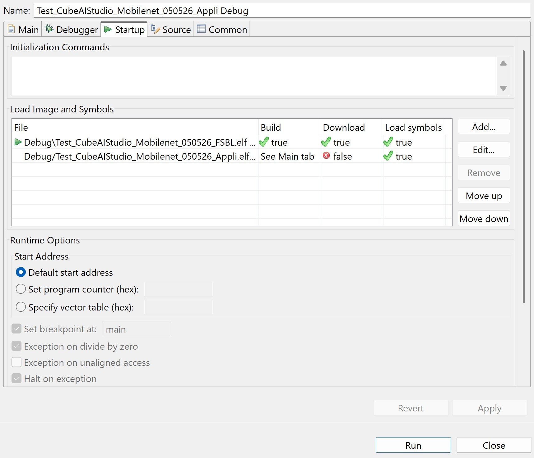
Click Run.
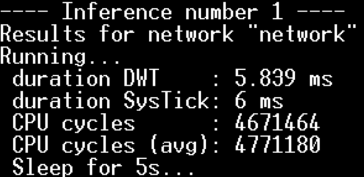
Open a serial terminal and connect to the board through Virtual COM Port (speed: 115200 bauds). Inference output is displayed on the serial console every 5s (inference time and number of CPU cycles).
Next Steps 
Validate model accuracy — in STM32Cube AI Studio, run an on-target validation to compare C model performance metrics against the original model and measure inference time.
Explore other AI models — download pre-trained STM32-optimized models from the STM32 Model Zoo
Customize the application — add camera input or display output for a full end-to-end inference pipeline
Troubleshooting 
Build error — missing BSP headers: Verify that
aps256xx_conf_template.handmx66uw1g45g_conf_template.hwere renamed toaps256xx_conf.handmx66uw1g45g_conf.h, and thatstm32xxxx_hal.hwas replaced withstm32n6xx_hal.hinside each file.``NetworkRuntime<version>_CM55_GCC.a`` not found at link time: Verify that
../Middlewares/ST/AI/Libis set as a Library search path in the Appli project linker settings, and thatNetworkRuntime<version>_CM55_GCC.ais listed in Libraries, with the right version number.``STM32CubeAI_Studio_AI_Init`` undefined reference: Confirm all files from
AI/App/(app_x-cube-ai.c, etc.) were copied to../Application/User/Coreand that../Application/User/AIis in the Appli include paths.Board not detected in STM32CubeProgrammer: Make sure the board is in DEV mode (
BOOT1slider to “H” position) and that the correct USB-C port labeledSTLINK V3ECis used.Application crashes or does not start after flashing: In Run Configurations, confirm that Download is unchecked for the Appli binary entry and that the FSBL project is added to the launch configuration startup sequence.
Assets 
Test_CubeAIStudio_Mobilenet_050526.ioc - download the
.iocconfiguration file and open it with STM32CubeMX.AI model (
.tflite) — obtain a compatible model from the STM32 Model Zoo. This tutorial was validated with STM32Cube AI Studio v1.2.0.