
How to configure an example 
STM32Cube Software Examples are preconfigured to demonstrate specific use-cases. They are designed for easy experimentation and exploration of the STM32 microcontroller capabilities.
Configuration can be done through:
Compiler switches: Preprocessor defines to enable or disable features
Code modification: Direct editing of source files in your IDE
STM32CubeMX2: Graphical configuration tool for STM32 peripherals and resources
Note
Examples are educational demonstrations, not production-ready code. They prioritize clarity and reusability (as code snippets) over optimization and error handling.
Additionally, examples can be combined to create new scenarios, as explained in the Combining multiple use-cases section.
Configuration layers 
Examples follow a layered architecture with distinct configuration points at each layer. For a detailed explanation of the architecture, refer to Example architecture.
Note
Project structure
: This documentation uses the STM32Cube MCU Package folder structure.
For standalone projects, omit the
[board_name]/
level or
application/
level.
Files are located directly at the project top folder or in corresponding sub-folders.
See
Folder structures
for details on the folder structure and deliverables.
|
Layer |
Files |
Configuration method |
What can be changed |
|---|---|---|---|
|
Infrastructure |
|
Code editing |
Application scheduling, satellite services [1], error handling |
|
Application use-case |
|
Code editing |
Use-case logic, algorithm parameters, step sequences |
|
Application resources |
|
STM32CubeMX2 or code editing |
STM32 peripherals, clocks, pins, middleware, utilities, parts, memory layout |
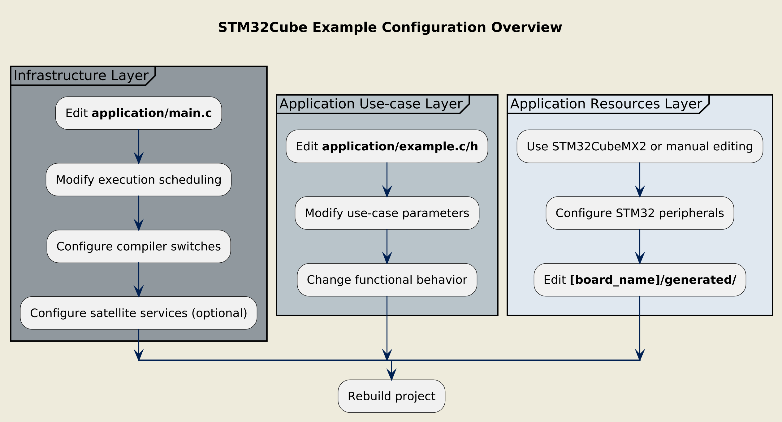
Overview of the configuration procedure
Infrastructure layer configuration 
File locations:
application/main.c
The infrastructure layer implements the execution control and invokes the system and satellite services initialization. For details on the infrastructure’s role and entry points, see the Example architecture.
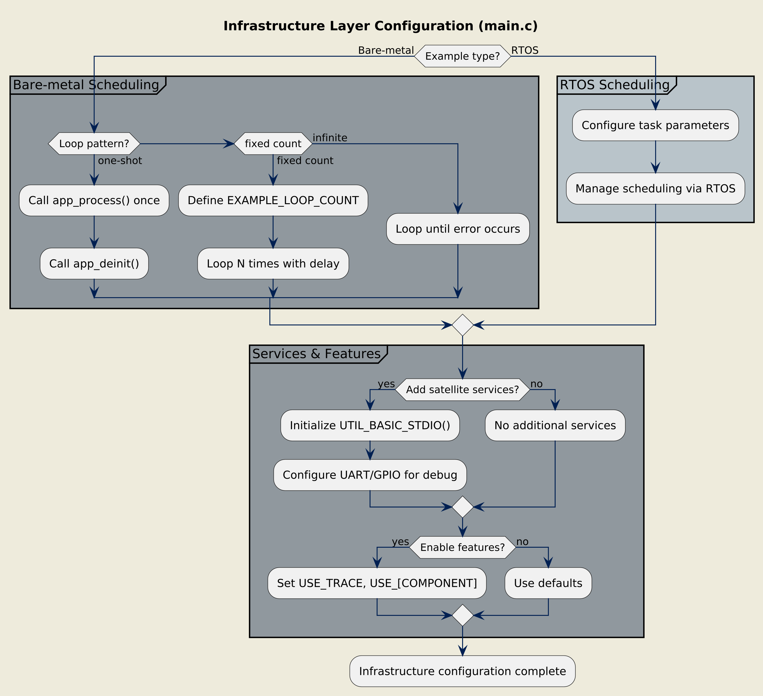
Configuring the infrastructure layer
Execution scheduling 
For bare-metal examples, change the execution mode by modifying the loop control in
main():
The default configuration for most examples:
/* Run app_process() once and call app_deinit() */
if (ExecStatus != EXEC_STATUS_ERROR)
{
  ExecStatus = app_process();
}

if (ExecStatus == EXEC_STATUS_OK)
{
  ExecStatus = app_deinit();
}
Execute the use-case a specific number of times:
/* @user: choose the number of process loops here */
#define EXAMPLE_LOOP_COUNT 20U

/* Run EXAMPLE_LOOP_COUNT times if no error occurs */
while ((ExecStatus != EXEC_STATUS_ERROR) && (ProcessLoops != 0U))
{
  ExecStatus = app_process();
  ProcessLoops--;
  HAL_Delay(EXAMPLE_LOOP_DELAY_MS);
}
Example: [eeprom_emulation/read_write](../../utilities/eeprom_emulation/read_write/application/main.c)
Continuously execute the use-case:
/* Run forever until an error occurs */
while (ExecStatus != EXEC_STATUS_ERROR)
{
  ExecStatus = app_process();
  HAL_Delay(EXAMPLE_LOOP_DELAY_MS);
}
For RTOS examples, the scheduling is managed by the RTOS and typically does not require modification in
main.c.
Instead, configure task parameters and scheduling policies within the RTOS configuration files or through STM32CubeMX2.
Satellite services 
If not already present, it is possible to add services not used by the main use-case but needed for observability or measurements:
if (mx_system_init() != SYSTEM_OK)
{
  ExecStatus = EXEC_STATUS_ERROR;
}
else
{
  /* Initialize the Basic STDIO component, pass a UART handle */
  #if defined(USE_TRACE) && USE_TRACE != 0
    UTIL_BASIC_STDIO_Init(mx_basic_stdio_gethandle());
  #endif

  /* Initialize example peripherals */
  ExecStatus = app_init();
}
Note
The initialization of satellite services happens after
mx_system_init()
but before
app_init().
Compiler switches 
Application-level compiler switches control features like logging and error handling.
IDE-managed switches 
Configure through your IDE’s preprocessor definitions:
|
Switch |
Default |
Description |
|---|---|---|
|
|
|
Enables trace output via
|
|
Other component switch |
Component-specific default |
Refer to component documentation |
CubeMX2-managed switches 
Located in
[board_name]/user_modifiable/Pre_Include_Global.h:
|
Switch |
Description |
|---|---|
|
|
Uses external oscillator and board-dependent values (such as
|
|
Any other configurable component switch managed at application level |
Refer to STM32CubeMX2 graphical user interface for available options and descriptions. |
These switches are automatically managed by STM32CubeMX2 code generation and should not be modified manually, except when not using STM32CubeMX2.
Application use-case layer configuration 
File locations:
application/example.c,
application/example.h
The use-case layer implements the functional logic using hardware-agnostic code.
For code structure details, see the Example architecture.
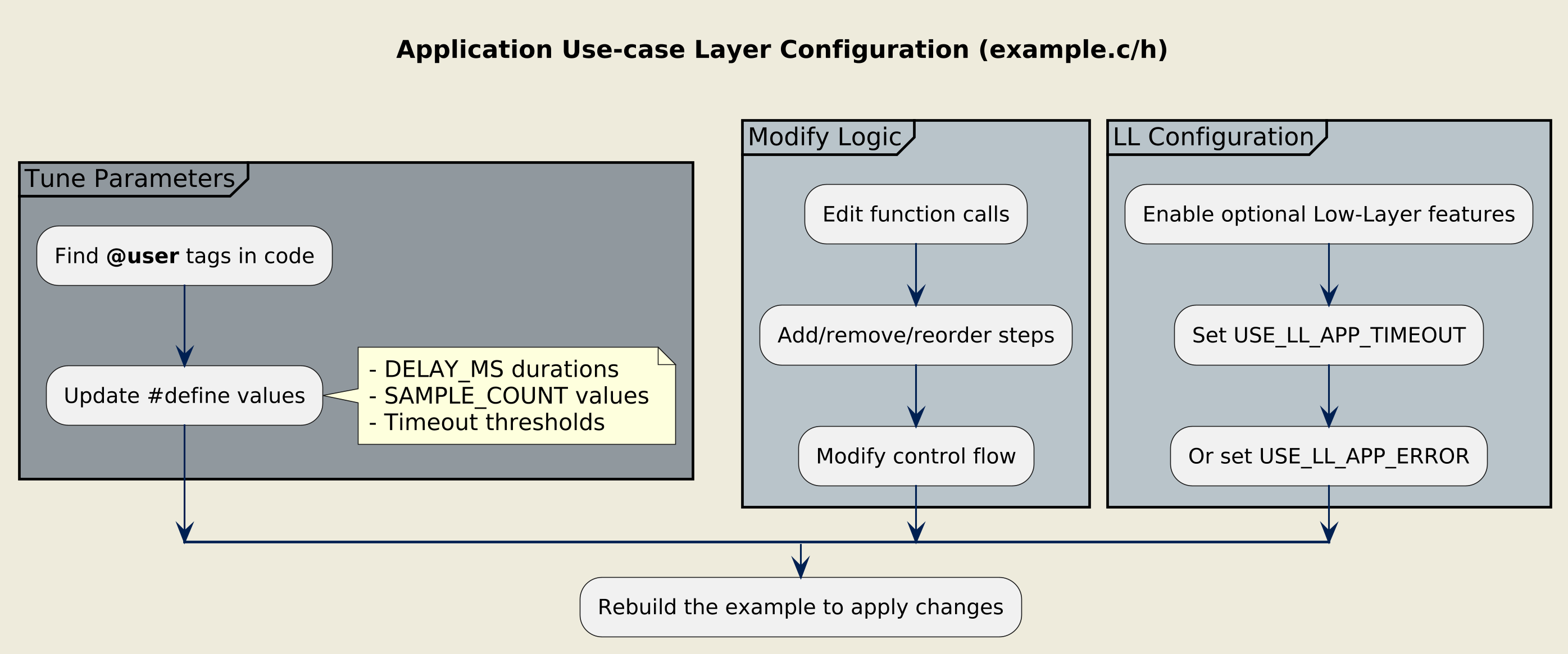
Configuring the use-case layer
User-configurable parameters 
Look for the
@user
tag in comments to identify the most common configuration points:
/* Private define ------------------------------------------------------------*/

/* @user: Time during which the LSI will be disabled */
#define LSI_DISABLE_DELAY_MS 2000U

/* @user: Number of ADC samples to average */
#define ADC_SAMPLE_COUNT 10U
Modifying use-case logic 
Change the behavior by editing function calls and control flow:
app_status_t app_process(void)
{
  /* Step 2: Disable LSI */
  if (HAL_RCC_LSI_Disable() != HAL_OK)
  {
    goto _app_process_exit;
  }
  PRINTF("[INFO] Step 2: LSI disabled.\n");

  /* @user: Modify delay duration here */
  HAL_Delay(LSI_DISABLE_DELAY_MS);

  /* Step 3: Re-enable LSI */
  if (HAL_RCC_LSI_Enable() != HAL_OK)
  {
    goto _app_process_exit;
  }

  return_status = EXEC_STATUS_OK;

_app_process_exit:
  return return_status;
}
You can add new steps, remove existing ones, or change the sequence to create custom scenarios.
LL-specific compiler switches 
Low-Layer (LL) examples may include optional features controlled by switches in
ll_example.h:
/* Exported constants --------------------------------------------------------*/
#ifndef USE_LL_APP_TIMEOUT
#define USE_LL_APP_TIMEOUT 0U
#endif /* USE_LL_APP_TIMEOUT */

#ifndef USE_LL_APP_ERROR
#define USE_LL_APP_ERROR 0U
#endif /* USE_LL_APP_ERROR */
When these switches exist:
|
Switch |
Description |
|---|---|
|
|
Enables timeout management in polling loops. |
|
|
Enables error checking and handling (error flags and error callbacks). |
Change the values in IDE project settings (preferred) or directly in
ll_example.h
to enable these features (set to
1U).
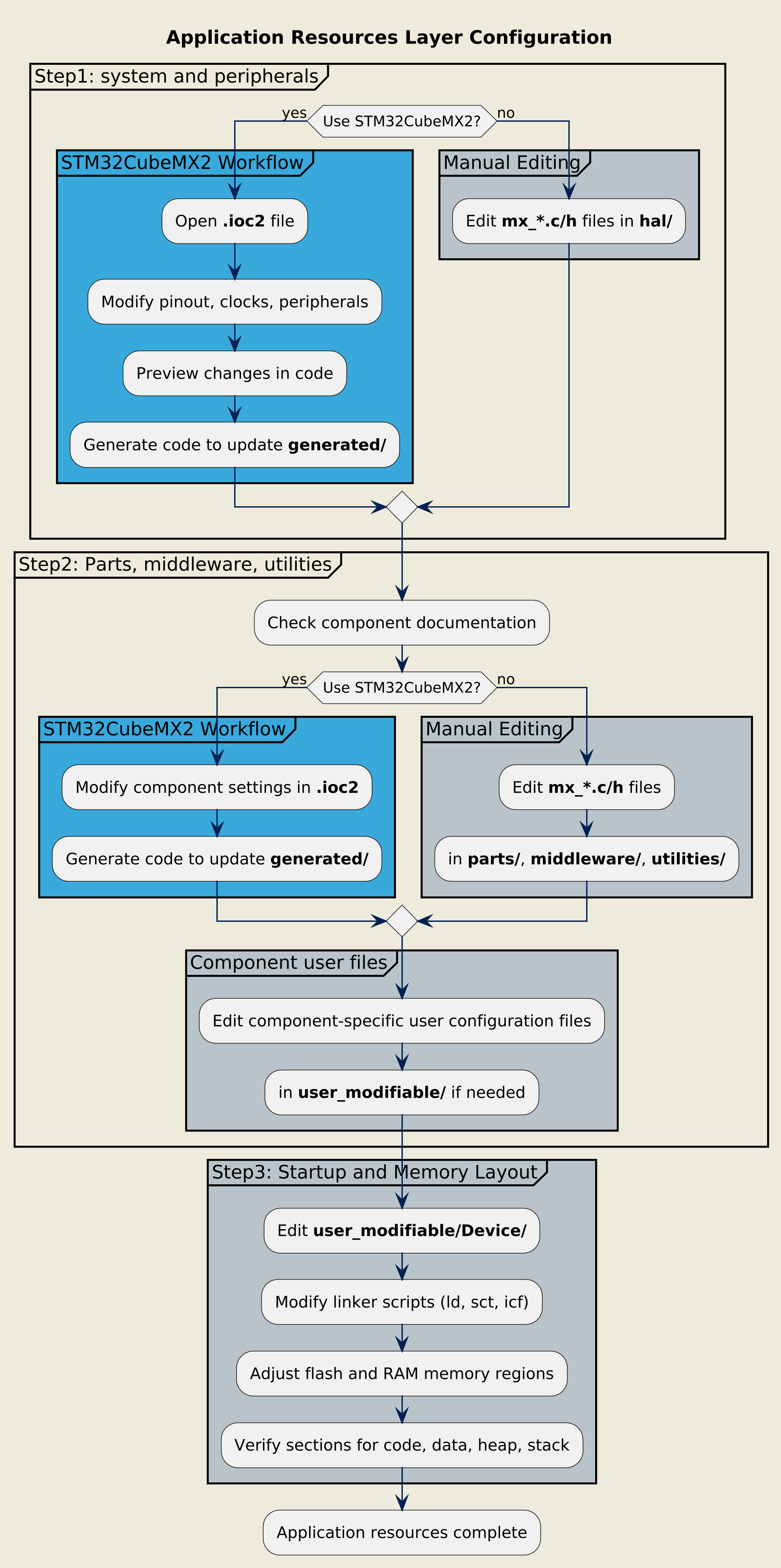
Application resources layer configuration 
This layer configures STM32 peripherals, board parts, middleware, and utilities. For details on the generated files and naming conventions, see Example architecture.
Configuring the resources layer
Peripherals and components 
These are the steps 1 and 2 in the diagram above.
File locations:
generated/hal/,
generated/parts/,
generated/middleware/[mw-name]/,
generated/utilities/[utility-name]/
Configuring with STM32CubeMX2 
STM32CubeMX2 provides graphical configuration tools for STM32 resources. Refer to the STM32CubeMX2 documentation for complete usage details.
Open the project
Open the
.ioc2file:[example_name].ioc2
Modify configuration
Use STM32CubeMX2 panels to change:
Pinout: GPIO assignments, alternate functions
Clock tree: System clocks, peripheral clocks
Peripheral configuration: Instance parameters, modes, interrupts
Configurable middleware: RTOS settings, etc.
Configurable parts: LED, button, sensor settings
Configurable utilities: utilities settings
Preview changes
Use the Code Preview feature to see exactly what code will be generated before applying changes:
Review modified files
Check for unintended changes
Verify aliases and user labels
Apply changes
You have two options:
Generate all configuration code to update the
generated/folder:
All
mx_*.candmx_*.hfiles are regeneratedIDE project files are updated
User code in
application/is preservedCopy specific code snippets from the Code Preview into existing files:
More control over what changes
Useful for small adjustments
Risk of inconsistency if not careful
Warning
Regenerating code overwrites all files in the
generated/
folder.
Never modify generated files directly. Use the
Code Preview
to verify changes before generation.
Configuring without STM32CubeMX2 
Modify configuration by editing files in the
generated/
folder:
[board_name]/generated/
├── hal/
│   ├── mx_adc1.c         # ADC1 peripheral configuration
│   ├── mx_i2c1.c         # I2C1 peripheral configuration
│   ├── mx_gpio_default.c # GPIO configuration
│   └── mx_hal_def.h      # Aliases for hardware abstraction
├── parts/
│   └── mx_led.h          # LED part driver aliases
└── utilities/
    └── eeprom_emul/      # EEPROM emulation configuration
Each
mx_[pppi].c
file handles one peripheral instance’s configuration using HAL (or LL) initialization APIs.
Warning
Manual edits to
generated/
files will be overwritten if you later use STM32CubeMX2 to regenerate code. Document your changes or avoid mixing manual and STM32CubeMX2 workflows.
Component configuration files 
Some middleware and utilities have their own user configuration files (typically in
user_modifiable/).
Refer to each component’s documentation for configuration details.
User-modifiable files 
The
user_modifiable/
folder contains files that can be modified directly by the user:
[board_name]/user_modifiable/
├── [IDE]/
│   └── Pre_Include_Global.h          # Global preprocessor switches
├── Device/
│   └── STM32[xxx]/
│       ├── startup_stm32xxx.c    # Device startup code
│       ├── system_stm32xxx.c     # System initialization
│       ├── stm32xxx_flash.ld     # GCC linker script
│       ├── stm32xxx_flash.sct    # ARMCC scatter file
│       └── stm32xxx_flash.icf    # IAR linker script
Memory layout modification :
Edit linker scripts to change:
Flash and RAM sizes
Memory region placement (CODE, DATA, BSS, HEAP, STACK)
Special sections (such as DMA buffers, shared memory)
Refer to your toolchain documentation for linker script syntax.
Example: GPIO configuration 
Scenario
: Change the toggle output GPIO from PA5 to PB5 in the
hal/gpio/toggle/
example for the board NUCLEO-C562RE.
Open
hal_gpio_toggle.ioc2in STM32CubeMX2In the Pinout view, find the toggle pin (PA5) and disable it
Configure PB5 as GPIO output and assign the user label
MX_EXAMPLE_GPIOUse Code Preview to verify:
mx_gpio_default.cnow initializes PB5 instead of PA5The pin configuration reflects the new GPIO port
Generate code to update the
generated/folderRebuild the project (no changes needed in
example.c)
Open
mx_gpio_default.cin thegenerated/hal/folderChange the GPIO initialization code to configure PB5 instead of PA5
Update
mx_gpio_default.hto define the correct port and pin aliases forMX_EXAMPLE_GPIO_PORTandMX_EXAMPLE_GPIO_PINRebuild the project (no changes needed in
example.c)
Expected changes:
|
Initial code |
Updated code |
|---|---|
|
mx_gpio_default.c system_status_t mx_gpio_default_init(void)
{
hal_gpio_config_t gpio_config;
HAL_RCC_GPIOA_EnableClock();
/*
GPIO pin labels :
PA5 ---------> PA5, MX_EXAMPLE_GPIO
*/
/* Configure PA5 GPIO pin in output mode */
gpio_config.mode = HAL_GPIO_MODE_OUTPUT;
gpio_config.speed = HAL_GPIO_SPEED_FREQ_LOW;
gpio_config.pull = HAL_GPIO_PULL_NO;
gpio_config.output_type = HAL_GPIO_OUTPUT_PUSHPULL;
gpio_config.init_state = PA5_INIT_STATE;
if (HAL_GPIO_Init(PA5_PORT, PA5_PIN, &gpio_config) != HAL_OK)
{
return SYSTEM_PERIPHERAL_ERROR;
}
return SYSTEM_OK;
}
mx_gpio_default.h /* Primary aliases for GPIO PA5 pin */
#define PA5_PORT HAL_GPIOA
#define PA5_PIN HAL_GPIO_PIN_5
#define PA5_INIT_STATE HAL_GPIO_PIN_RESET
#define PA5_ACTIVE_STATE HAL_GPIO_PIN_SET
#define PA5_INACTIVE_STATE HAL_GPIO_PIN_RESET
/* Secondary aliases for GPIO PA5 pin */
#define MX_EXAMPLE_GPIO_PORT HAL_GPIOA
#define MX_EXAMPLE_GPIO_PIN HAL_GPIO_PIN_5
#define MX_EXAMPLE_GPIO_INIT_STATE HAL_GPIO_PIN_RESET
#define MX_EXAMPLE_GPIO_ACTIVE_STATE HAL_GPIO_PIN_SET
#define MX_EXAMPLE_GPIO_INACTIVE_STATE HAL_GPIO_PIN_RESET
|
mx_gpio_default.c system_status_t mx_gpio_default_init(void)
{
hal_gpio_config_t gpio_config;
HAL_RCC_GPIOB_EnableClock();
/*
GPIO pin labels :
PB5 ---------> PB5, MX_EXAMPLE_GPIO
*/
/* Configure PB5 GPIO pin in output mode */
gpio_config.mode = HAL_GPIO_MODE_OUTPUT;
gpio_config.speed = HAL_GPIO_SPEED_FREQ_LOW;
gpio_config.pull = HAL_GPIO_PULL_NO;
gpio_config.output_type = HAL_GPIO_OUTPUT_PUSHPULL;
gpio_config.init_state = PB5_INIT_STATE;
if (HAL_GPIO_Init(PB5_PORT, PB5_PIN, &gpio_config) != HAL_OK)
{
return SYSTEM_PERIPHERAL_ERROR;
}
return SYSTEM_OK;
}
mx_gpio_default.h /* Primary aliases for GPIO PB5 pin */
#define PB5_PORT HAL_GPIOB
#define PB5_PIN HAL_GPIO_PIN_5
#define PB5_INIT_STATE HAL_GPIO_PIN_RESET
#define PB5_ACTIVE_STATE HAL_GPIO_PIN_SET
#define PB5_INACTIVE_STATE HAL_GPIO_PIN_RESET
/* Secondary aliases for GPIO PB5 pin */
#define MX_EXAMPLE_GPIO_PORT HAL_GPIOB
#define MX_EXAMPLE_GPIO_PIN HAL_GPIO_PIN_5
#define MX_EXAMPLE_GPIO_INIT_STATE HAL_GPIO_PIN_RESET
#define MX_EXAMPLE_GPIO_ACTIVE_STATE HAL_GPIO_PIN_SET
#define MX_EXAMPLE_GPIO_INACTIVE_STATE HAL_GPIO_PIN_RESET
|
Note
Thanks to the hardware abstraction via
MX_EXAMPLE_GPIO_PORT
and
MX_EXAMPLE_GPIO_PIN
aliases, the application code in
example.c
requires no modification.
Summary 
|
What to configure |
Method |
Where |
|---|---|---|
|
Execution scheduling |
Edit code |
|
|
Console logs |
IDE preprocessor defines |
|
|
Use-case sequence/parameters |
Edit code |
|
|
LL optional features |
Edit IDE settings or header file |
|
|
STM32 peripherals |
STM32CubeMX2 or edit
|
|
|
Part drivers |
STM32CubeMX2 or edit
|
|
|
Middleware |
STM32CubeMX2 or edit
|
|
|
Utilities |
STM32CubeMX2 or edit
|
|
|
Memory layout |
Edit linker scripts |
|
Combining multiple use-cases 
Examples follow consistent architectural patterns, making it straightforward to merge two use-cases:
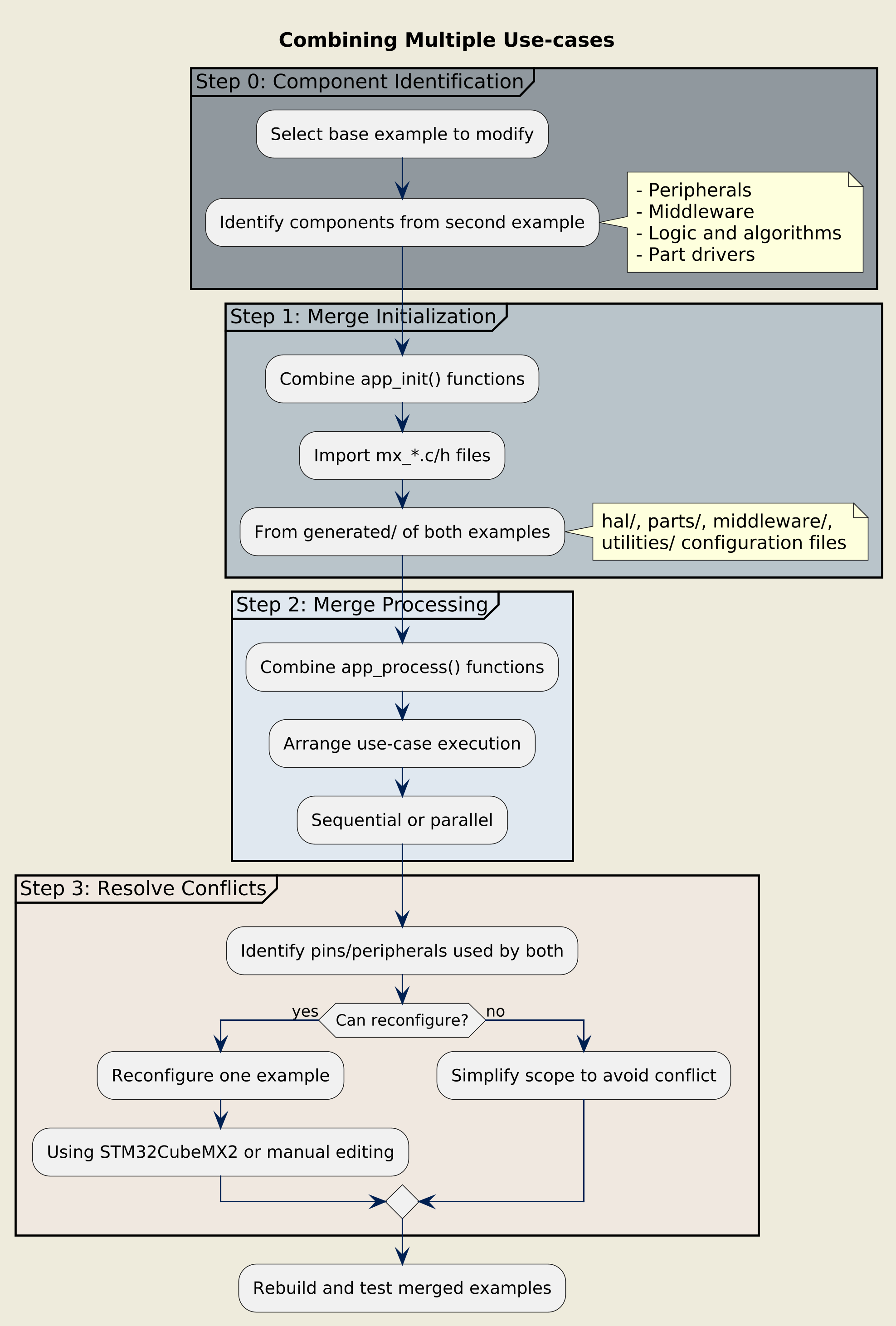
Procedure for merging use-cases
- Step 0 : Identify the software components to add in the modified example.
-
Determine which peripherals, middleware, and logic from the second example you want to integrate.
- Step 1 : Merge initialization functions
-
Combine the
app_init()functions from both examples. Import required resource configuration files (mx_*.c/h) from thegenerated/folder of both examples. - Step 2 : Merge processing functions
-
Combine the
app_process()functions. Ensure both use-cases’ steps run in the desired sequence or parallel structure. - Step 3 : Resolve resource conflicts
-
If both examples use the same peripheral instance or pins, reconfigure one using STM32CubeMX2 or manually edit the
mx_*.cfiles.
Warning
When merging examples, verify that resource configurations (pins, DMA channels, interrupts) do not conflict.