
 st-edge-ai-core

Use USB-CDC device driver for validation 
Purpose 
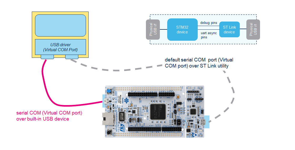
This article is a how-to to explain how to enable the USB-CDC profile to perform faster the validation on the board. A client USB device with the STM32 Communication Device Class (i.e. Virtual COM Port) is used as communication link with the host. It allows to avoid the overhead of the ST Link bridge connecting the UART pins to/from the ST Link USB port. However, a STM32 Nucleo or Discovery board with a built-in USB device peripheral is requested.
Note
This how-to is illustrated with a Nucleo H743ZI, but all STM32 development board with a built-in USB device peripheral can be used. The associated USB driver (including its USB-CDC middleware) is used w/o modification, setting or debug of this stack is out of this article.
Project creation 
To create a firmware with the USB CDC driver, a standard project should be created with the USB stack enabled, including the USB Device middleware with the Communication Device Class (Virtual Port Com). Default options are used. For the AI part, the core and validation application should be selected (refer to [UM]). IDE project should be generated (automatic validation on target feature is not supported).
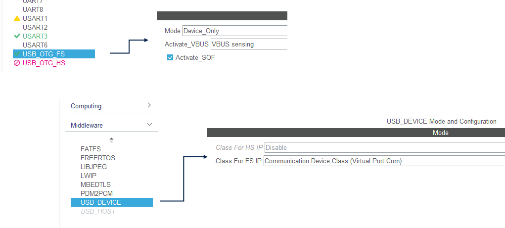
The generated IDE project is ready to be used. Before to compile the project, the following adaptations are requested to use the USB-CDC client drivers:
As illustrated with a STM32CubeIDE-based project, the
USE_USB_CDC_CLASSC-define should be globally defined and set to1to enable the low-level services, part of theaiTestUtility.cfile.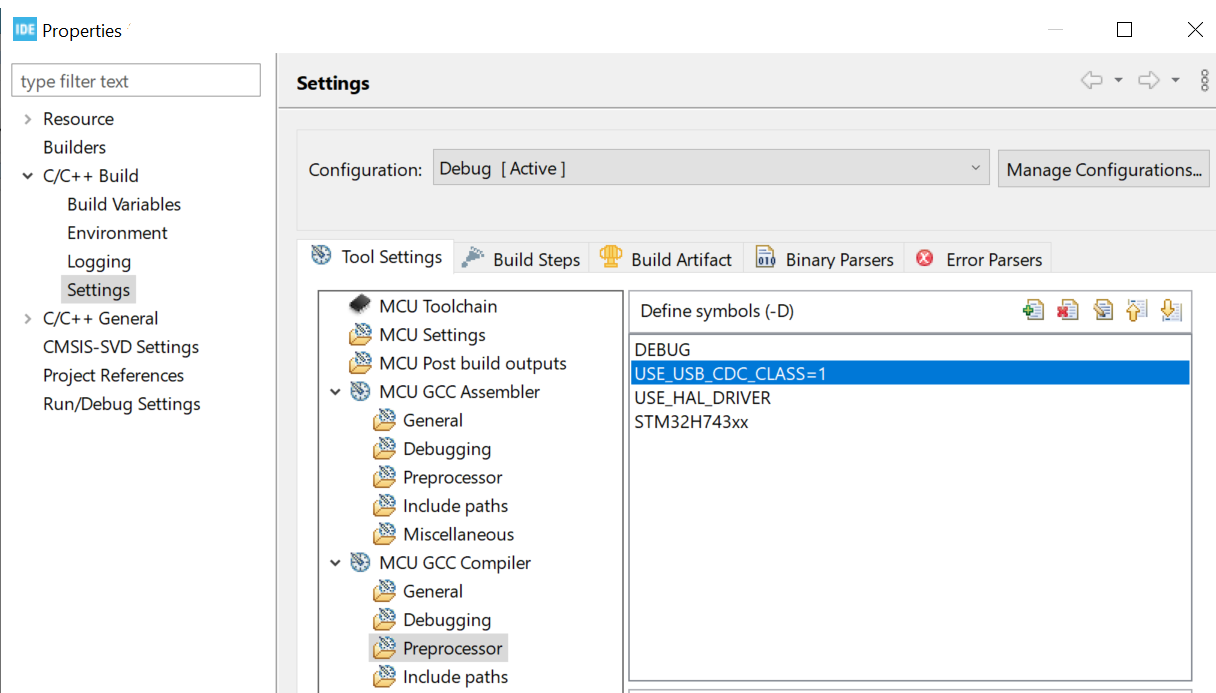
Two functions from the USB-CDC application i/f code (
USB_DEVICE/App/usbd_cdc_if.cfile) should be updated with the following extra code.First part allows to manage the in-coming data in the CDC USB call-back.
static int8_t CDC_Receive_FS(uint8_t* Buf, uint32_t *Len)
{
/* USER CODE BEGIN 6 */
#if defined(USE_USB_CDC_CLASS) && USE_USB_CDC_CLASS == 1
    extern void ioPushInUserUsb(uint8_t *pw, uint32_t *len);
    ioPushInUserUsb(Buf, Len);
#endif
USBD_CDC_SetRxBuffer(&hUsbDeviceFS, &Buf[0]);
USBD_CDC_ReceivePacket(&hUsbDeviceFS);
return (USBD_OK);
/* USER CODE END 6 */
}
Second part is the minimum code, requested by the Python host module which is used to perform the validation over a serial com. It prevents an issue during the set-up phase.
static int8_t CDC_Control_FS(uint8_t cmd, uint8_t* pbuf, uint16_t length)
{
/* USER CODE BEGIN 5 */
...
    case CDC_GET_LINE_CODING:

            if (length == 7) {
            *(uint32_t *)pbuf = 115200;
            pbuf[4] = 0;
            pbuf[5] = 0;
            pbuf[6] = 8;
            }
    break;

return (USBD_OK);
/* USER CODE END 5 */
}
Optionally, the default size of the USB RX and TX buffers can be reduced to limit the usage
of the RAM (
USB_DEVICE/App/usbd_cdc_if.h
file)
#define APP_RX_DATA_SIZE  64  /* instead 2048 */
#define APP_TX_DATA_SIZE  64  /* instead 2048 */
Validation on target 
After this adaptation phase of the code, the firmware is generated and flashed on the board. During the
initialization of the firmware, a phase of enumeration is performed with the host to discover
the profile and to create a virtual com port. Name and value of this new COM port is
system dependent. In this example, the new COM port appears as
COM8
(Windows® 10 environment).
Normal validation on the board can be executed, through the UI (
Baudrate
value is not considered)
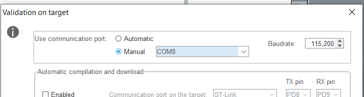
or through the command line
$ stm32ai validate -m <model_file> --target stm32 --mode target -d COM8
Performance improvement 
With a Nucleo H743ZI board (@96MHz) and a typical floating-point model (
--full
option and a batch of
100
samples are used).
|
Used COM port |
execution time |
|---|---|
|
ST Link + baudrate 115200 |
27s |
|
ST Link + baudrate 921600 |
14,4s |
|
USB-CDC full speed |
8.7s |