
HAL implementation built upon LL services 
The concept 
The hardware abstraction layer (HAL) provides a high-level, user-friendly interface for hardware peripherals, built on top of the low-layer (LL) drivers. HAL2 simplifies peripheral configuration and control by abstracting the complexities of LL drivers, eliminating the need for direct register-level programming. This layered design balances ease of use, control, and efficiency, ensuring portability across hardware platforms while leveraging the performance and precision of LL drivers.
HAL2 depends on LL drivers for register access, promoting consistent and reliable hardware interaction. This separation improves code maintainability and readability, with any LL driver updates automatically benefiting HAL.
Key HAL features include parameter validation, state management, and logical sequences for configuration and operation, enhancing reliability through return values and callbacks. Meanwhile, LL drivers provide efficient, low-level APIs aligned with STM32 reference manuals, offering direct hardware access and optimal performance. Built upon the efficient hardware management of LL, HAL simplifies peripheral control.
In short, the HAL-over-LL principle aims to:
Deliver a clear and comprehensive LL sequence within the HAL implementation.
Facilitate easy migration from HAL to LL by providing a well-defined LL sequence.
Establish a clearly layered architecture, with HAL built over LL at the function level rather than the register level.
Align STM32CubeMX2 LL code generation for configuration sequences with the validated HAL implementation sequences.
Note
Some system HALs, such as Cortex, are built on top of CMSIS core services. In these cases, the HAL does not access registers directly when an LL driver or CMSIS core service is available.
For peripherals without an LL driver, like HAL FDCAN, the HAL driver can perform direct register access.
Warning
In HAL2, the LL initialization functions previously found in the
stm32tnxx_ll_ppp.c
files are removed. Only the LL header files (
stm32tnxx_ll_ppp.h) containing static inline functions remain. To initialize peripherals using the LL layer, users must use STM32CubeMX2 code generation, which produces initialization sequences based on these static inline functions. This generated code offers improved footprint optimization compared to the former LL Init functions in the
stm32tnxx_ll_ppp.c
files.
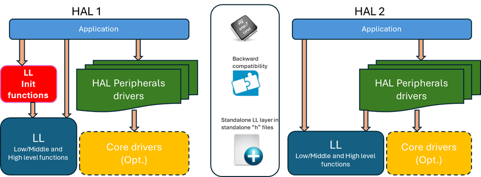
As shown by the diagram, the LL contains low-, middle-, and high-level functions. The table below provides examples corresponding to each level.
|
Level |
Description |
Example(s) |
|---|---|---|
|
Low level |
|
#define LL_TIM_WRITE_REG(instance, reg, value) WRITE_REG((instance)->reg, (value))
#define LL_TIM_READ_REG(instance, reg) READ_REG((instance)->reg)
|
|
Middle level |
One-shot (atomic) operations and elementary
|
__STATIC_INLINE void LL_ADC_Enable(ADC_TypeDef *p_adc)
{
  MODIFY_REG(p_adc->CR, LL_ADC_CR_BITS_PROPERTY_RS, ADC_CR_ADEN);
}

__STATIC_INLINE void LL_LPTIM_SetCounterMode(LPTIM_TypeDef *lptimx, uint32_t counter_mode)
{
  MODIFY_REG(lptimx->CFGR, LPTIM_CFGR_COUNTMODE, counter_mode);
}
|
|
High level |
Configuration functions that cover full standalone operations on relative peripheral registers |
__STATIC_INLINE void LL_I2C_ConfigOwnAddress1(I2C_TypeDef *p_i2c, uint32_t own_address1, uint32_t own_addr_size)
{
  WRITE_REG(p_i2c->OAR1, I2C_OAR1_OA1EN | own_address1 | own_addr_size);
}

__STATIC_INLINE void LL_RTC_TIME_Config(uint32_t Format12_24, uint32_t Hours, uint32_t Minutes,
                                        uint32_t Seconds)
{
  uint32_t temp;

  temp = Format12_24 | \
         (((Hours & 0xF0U) << (RTC_TR_HT_Pos - 4U)) | ((Hours & 0x0FU) << RTC_TR_HU_Pos))      | \
         (((Minutes & 0xF0U) << (RTC_TR_MNT_Pos - 4U)) | ((Minutes & 0x0FU) << RTC_TR_MNU_Pos))| \
         (((Seconds & 0xF0U) << (RTC_TR_ST_Pos - 4U)) | ((Seconds & 0x0FU) << RTC_TR_SU_Pos));
  WRITE_REG(RTC->TR, temp);
}
|
HAL implementation with LL inline functions 
The HAL internally uses LL inline functions rather than direct register access. This design detail does not affect user applications, so no specific migration steps are needed when moving from HAL1 to HAL2.
However, understanding this concept is valuable for users who wish to transition from HAL APIs to equivalent LL APIs. Such a transition can optimize application footprint by replacing higher-level HAL calls with streamlined LL sequences, eliminating HAL logical checks and state management.
|
HAL1 |
HAL2 |
|---|---|
HAL_StatusTypeDef HAL_DCACHE_Invalidate(DCACHE_HandleTypeDef *hdcache)
{
  ...
  /* Set no operation on address range */
  MODIFY_REG(hdcache->Instance->CR, DCACHE_CR_CACHECMD, 0U);
  /* Launch cache invalidation */
  SET_BIT(hdcache->Instance->CR, DCACHE_CR_CACHEINV);
  ...
}
|
hal_status_t HAL_DCACHE_Invalidate(hal_dcache_handle_t *hdcache)
{
  ...
  /* Set no operation on address range */
  LL_DCACHE_SetCommand(p_dcachex, LL_DCACHE_COMMAND_NO_OPERATION);
  /* Launch DCACHE invalidation */
  LL_DCACHE_Invalidate(p_dcachex);
  ...
}
|
Define statements and enumerations redirected to LL equivalents 
In HAL1, define statements and enumerations for possible values rely on register bitfield define statements from CMSIS device header files. In HAL2, these are mapped to equivalent LL defines, enabling a smoother transition from HAL-based to LL-based applications.
|
HAL1 |
HAL2 |
|---|---|
#define RCC_MCO1SOURCE_NOCLOCK 0x00000000U
#define RCC_MCO1SOURCE_SYSCLK  RCC_CFGR1_MCOSEL_0
#define RCC_MCO1SOURCE_MSI     RCC_CFGR1_MCOSEL_1
#define RCC_MCO1SOURCE_HSI     (RCC_CFGR1_MCOSEL_0 | RCC_CFGR1_MCOSEL_1)
#define RCC_MCO1SOURCE_HSE     RCC_CFGR1_MCOSEL_2
#define RCC_MCO1SOURCE_PLL1CLK (RCC_CFGR1_MCOSEL_0 | RCC_CFGR1_MCOSEL_2)
#define RCC_MCO1SOURCE_LSI     (RCC_CFGR1_MCOSEL_1 | RCC_CFGR1_MCOSEL_2)
#define RCC_MCO1SOURCE_LSE     (RCC_CFGR1_MCOSEL_0 | RCC_CFGR1_MCOSEL_1 | RCC_CFGR1_MCOSEL_2)
#define RCC_MCO1SOURCE_HSI48   RCC_CFGR1_MCOSEL_3
#define RCC_MCO1SOURCE_MSIK    (RCC_CFGR1_MCOSEL_0 | RCC_CFGR1_MCOSEL_3)


#define RCC_MCODIV_1   0x00000000U
#define RCC_MCODIV_2   RCC_CFGR1_MCOPRE_0
#define RCC_MCODIV_4   RCC_CFGR1_MCOPRE_1
#define RCC_MCODIV_8   (RCC_CFGR1_MCOPRE_0 | RCC_CFGR1_MCOPRE_1)
#define RCC_MCODIV_16  RCC_CFGR1_MCOPRE_2


void HAL_RCC_MCOConfig(uint32_t RCC_MCOx, uint32_t RCC_MCOSource, uint32_t RCC_MCODiv)
{
  ...
  MODIFY_REG(RCC->CFGR1, (RCC_CFGR1_MCOSEL | RCC_CFGR1_MCOPRE), (RCC_MCOSource | RCC_MCODiv));
}
|
typedef enum
{
  HAL_RCC_MCO_SRC_NOCLOCK = LL_RCC_MCO1SOURCE_NOCLOCK,
  HAL_RCC_MCO_SRC_SYSCLK  = LL_RCC_MCO1SOURCE_SYSCLK,
  HAL_RCC_MCO_SRC_MSI     = LL_RCC_MCO1SOURCE_MSIS,
  HAL_RCC_MCO_SRC_HSI     = LL_RCC_MCO1SOURCE_HSI,
  HAL_RCC_MCO_SRC_HSE     = LL_RCC_MCO1SOURCE_HSE,
  HAL_RCC_MCO_SRC_PLL1CLK = LL_RCC_MCO1SOURCE_PLLCLK,
  HAL_RCC_MCO_SRC_LSI     = LL_RCC_MCO1SOURCE_LSI,
  HAL_RCC_MCO_SRC_LSE     = LL_RCC_MCO1SOURCE_LSE,
  HAL_RCC_MCO_SRC_HSI48   = LL_RCC_MCO1SOURCE_HSI48,
  HAL_RCC_MCO_SRC_MSIK    = LL_RCC_MCO1SOURCE_MSIK,
} hal_rcc_mco_src_t;

typedef enum
{
  HAL_RCC_MCO_DIV1  = LL_RCC_MCO1_DIV_1,
  HAL_RCC_MCO_DIV2  = LL_RCC_MCO1_DIV_2,
  HAL_RCC_MCO_DIV4  = LL_RCC_MCO1_DIV_4,
  HAL_RCC_MCO_DIV8  = LL_RCC_MCO1_DIV_8,
  HAL_RCC_MCO_DIV16 = LL_RCC_MCO1_DIV_16,
} hal_rcc_mco_div_t;

void HAL_RCC_SetConfigMCO(hal_rcc_mco_src_t mco_src, hal_rcc_mco_div_t mco_div)
{
  ...
  LL_RCC_ConfigMCO((uint32_t)mco_src, (uint32_t)mco_div);
}
|
#define GPIO_PIN_0     ((uint16_t)0x0001)
#define GPIO_PIN_1     ((uint16_t)0x0002)
#define GPIO_PIN_2     ((uint16_t)0x0004)
#define GPIO_PIN_3     ((uint16_t)0x0008)
#define GPIO_PIN_4     ((uint16_t)0x0010)
#define GPIO_PIN_5     ((uint16_t)0x0020)
#define GPIO_PIN_6     ((uint16_t)0x0040)
#define GPIO_PIN_7     ((uint16_t)0x0080)
#define GPIO_PIN_8     ((uint16_t)0x0100)
#define GPIO_PIN_9     ((uint16_t)0x0200)
#define GPIO_PIN_10    ((uint16_t)0x0400)
#define GPIO_PIN_11    ((uint16_t)0x0800)
#define GPIO_PIN_12    ((uint16_t)0x1000)
#define GPIO_PIN_13    ((uint16_t)0x2000)
#define GPIO_PIN_14    ((uint16_t)0x4000)
#define GPIO_PIN_15    ((uint16_t)0x8000)
#define GPIO_PIN_ALL   ((uint16_t)0xFFFF)
|
#define HAL_GPIO_PIN_0   LL_GPIO_PIN_0
#define HAL_GPIO_PIN_1   LL_GPIO_PIN_1
#define HAL_GPIO_PIN_2   LL_GPIO_PIN_2
#define HAL_GPIO_PIN_3   LL_GPIO_PIN_3
#define HAL_GPIO_PIN_4   LL_GPIO_PIN_4
#define HAL_GPIO_PIN_5   LL_GPIO_PIN_5
#define HAL_GPIO_PIN_6   LL_GPIO_PIN_6
#define HAL_GPIO_PIN_7   LL_GPIO_PIN_7
#define HAL_GPIO_PIN_8   LL_GPIO_PIN_8
#define HAL_GPIO_PIN_9   LL_GPIO_PIN_9
#define HAL_GPIO_PIN_10  LL_GPIO_PIN_10
#define HAL_GPIO_PIN_11  LL_GPIO_PIN_11
#define HAL_GPIO_PIN_12  LL_GPIO_PIN_12
#define HAL_GPIO_PIN_13  LL_GPIO_PIN_13
#define HAL_GPIO_PIN_14  LL_GPIO_PIN_14
#define HAL_GPIO_PIN_15  LL_GPIO_PIN_15
#define HAL_GPIO_PIN_ALL LL_GPIO_PIN_ALL
|