
LL_USART_Init and LL_USART_DeInit APIs migration 
The LL initialization and de-initialization functions previously available in the
stm32tnxx_ll_usart.c
files
within HAL1 are no longer present in HAL2.
In HAL2, all LL C files (
stm32tnxx_ll_usart.c) have been removed, leaving only the LL header files (
stm32tnxx_ll_usart.h)
that contain static inline functions.
If users need to initialize or de-initialize USART using the LL layer, they have two methods:
Utilize STM32CubeMX2 Code Generation: Rely on STM32CubeMX2 to generate code with the LL layer for USART initialization and de-initialization.
Replace manually the initialization and de-initialization functions: Replace the
LL_USART_InitandLL_USART_DeInitfunctions manually with equivalent sequences using the static inline functions provided in thestm32tnxx_ll_usart.hfile, tailored to their specific configuration and requirements.
This approach ensures that the initialization and de-initialization sequences are precisely addressing the given use case based on the LL static inline functions provided in the
stm32tnxx_ll_usart.h
header file.
The sequences offer improved footprint optimization compared to the previous LL initialization functions found in
stm32tnxx_ll_usart.c.
Related concept:
Method 1: Utilize STM32CubeMX2 Code Generation 
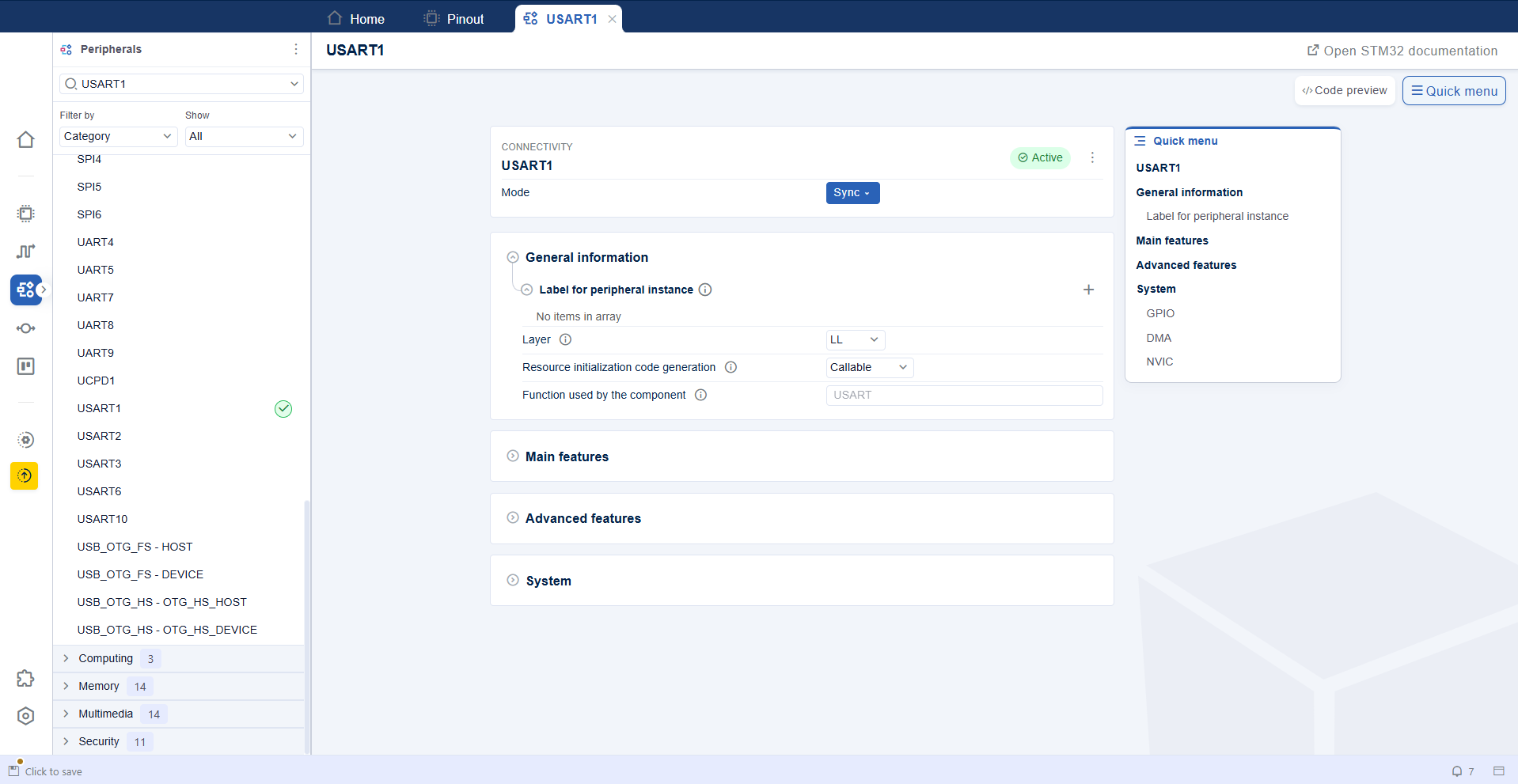
LL USART configuration panel 
Create a new project with STM32CubeMX2, start by enabling the USART instance as Sync, as shown in this example with the selected USART1.
Choose the LL layer for code generation.
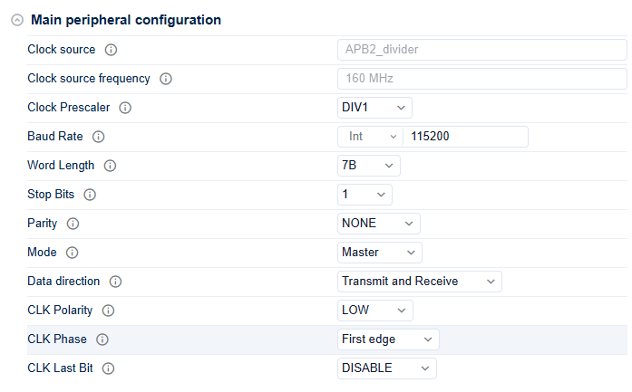
LL USART main features configuration 
Configure the USART main features.
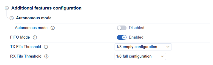
LL USART additional features configuration 
Configure the additional UART features if needed.
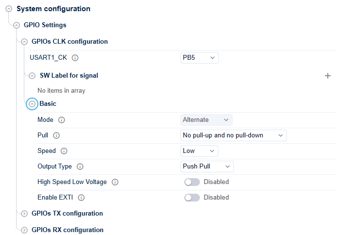
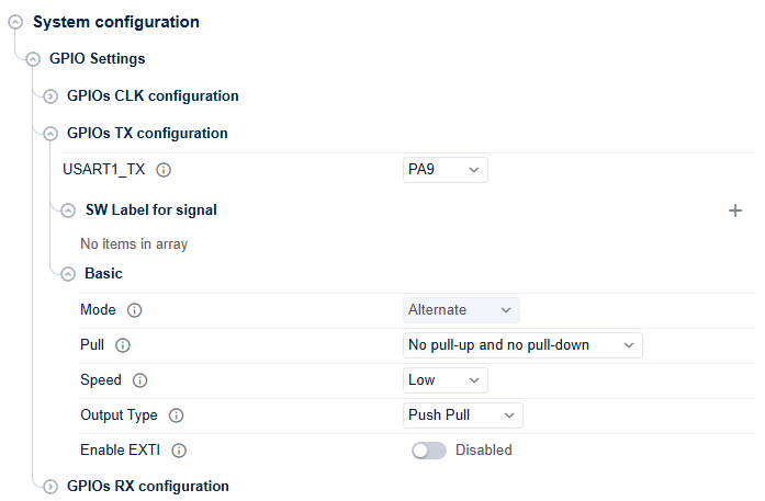
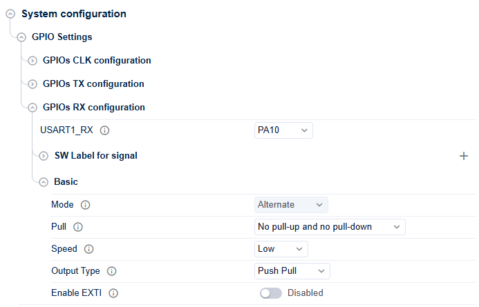
LL GPIO configuration 
Configure the
USART_CLK,
USART_TX``and


            the


            ``USART_RX
GPIO pins.
GPIO CLK configuration 
GPIO TX configuration 
GPIO RX configuration 
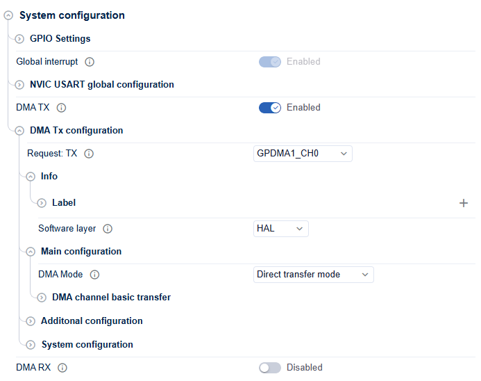
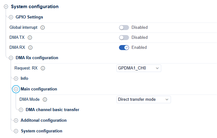
LL DMA configuration 
Configure the DMA for data reception as needed.
DMA TX configuration 
DMA RX configuration 
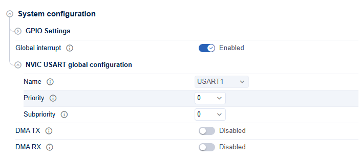
LL NVIC configuration 
Configure the NVIC in case of an interrupt.
Generated USART initialization sequence 
The USART initialization and de-initialization sequences are generated in the
mx_usart_ll_init
and
mx_usart_ll_deinit
functions in
mx_usart.c
file under
$YOUR_PROJECT_NAME$/$YOUR_PROJECT_NAME$_SW/generated/STM32Cube_CodeGen.
|
Topic |
Code Snippet HAL1 |
Code Snippet HAL2 |
|---|---|---|
|
Initialization and configuration sequence |
static void MX_USART1_Init(void)
{
  /* Peripheral clock enable */
  LL_APB2_GRP1_EnableClock(LL_APB2_GRP1_PERIPH_USART1);

  USART_InitStruct.BaudRate = 115200;
  USART_InitStruct.DataWidth = LL_USART_DATAWIDTH_8B;
  USART_InitStruct.Parity = LL_USART_PARITY_NONE;
  USART_InitStruct.TransferDirection = LL_USART_DIRECTION_TX_RX;
  USART_InitStruct.StopBits = LL_USART_STOPBITS_1;
  LL_USART_Init(USART1, &USART_InitStruct);
  USART_ClockInitStruct.ClockOutput = LL_USART_CLOCK_ENABLE;
  USART_ClockInitStruct.ClockPolarity = LL_USART_POLARITY_LOW;
  USART_ClockInitStruct.ClockPhase = LL_USART_PHASE_1EDGE;
  USART_ClockInitStruct.LastBitClockPulse = LL_USART_LASTCLKPULSE_NO_OUTPUT;
  LL_USART_ClockInit(USART1, &USART_ClockInitStruct);
  LL_USART_ConfigSyncMode(USART1);
  LL_USART_Enable(USART1);

  LL_GPIO_InitTypeDef GPIO_InitStruct = {0};
  GPIO_InitStruct.Pin = LL_GPIO_PIN_8|LL_GPIO_PIN_10;


  GPIO_InitStruct.Mode = LL_GPIO_MODE_ALTERNATE;


  GPIO_InitStruct.Speed = LL_GPIO_SPEED_FREQ_VERY_HIGH;


  GPIO_InitStruct.OutputType = LL_GPIO_OUTPUT_PUSHPULL;


  GPIO_InitStruct.Pull = LL_GPIO_PULL_NO;
  GPIO_InitStruct.Alternate = LL_GPIO_AF_15;
  LL_GPIO_Init(GPIOA, &GPIO_InitStruct);

  /* USART1 interrupt Init */
  NVIC_SetPriority(USART1_IRQn, NVIC_EncodePriority(NVIC_GetPriorityGrouping(),0, 0));
  NVIC_EnableIRQ(USART1_IRQn);

  /* USART1_TX Init */

  /* DMA controller clock enable */
  LL_AHB1_GRP1_EnableClock(LL_AHB1_GRP1_PERIPH_DMA1);


  LL_DMA_SetChannelSelection(DMA1, LL_DMA_STREAM_7, LL_DMA_CHANNEL_0);


  LL_DMA_SetDataTransferDirection(DMA1, LL_DMA_STREAM_7, LL_DMA_DIRECTION_MEMORY_TO_PERIPH);


  LL_DMA_SetStreamPriorityLevel(DMA1, LL_DMA_STREAM_7, LL_DMA_PRIORITY_LOW);

  LL_DMA_SetMode(DMA1, LL_DMA_STREAM_7, LL_DMA_MODE_NORMAL);
  LL_DMA_SetPeriphIncMode(DMA1, LL_DMA_STREAM_7, LL_DMA_PERIPH_NOINCREMENT);
  LL_DMA_SetMemoryIncMode(DMA1, LL_DMA_STREAM_7, LL_DMA_MEMORY_INCREMENT);
  LL_DMA_SetPeriphSize(DMA1, LL_DMA_STREAM_7, LL_DMA_PDATAALIGN_BYTE);
  LL_DMA_SetMemorySize(DMA1, LL_DMA_STREAM_7, LL_DMA_MDATAALIGN_BYTE);

  /* USART1_RX Init */


  LL_DMA_SetChannelSelection(DMA2, LL_DMA_STREAM_2, LL_DMA_CHANNEL_4);


  LL_DMA_SetDataTransferDirection(DMA2, LL_DMA_STREAM_2, LL_DMA_DIRECTION_PERIPH_TO_MEMORY);


  LL_DMA_SetStreamPriorityLevel(DMA2, LL_DMA_STREAM_2, LL_DMA_PRIORITY_LOW);


  LL_DMA_SetMode(DMA2, LL_DMA_STREAM_2, LL_DMA_MODE_NORMAL);
  LL_DMA_SetPeriphIncMode(DMA2, LL_DMA_STREAM_2, LL_DMA_PERIPH_NOINCREMENT);
  LL_DMA_SetMemoryIncMode(DMA2, LL_DMA_STREAM_2, LL_DMA_MEMORY_INCREMENT);
  LL_DMA_SetPeriphSize(DMA2, LL_DMA_STREAM_2, LL_DMA_PDATAALIGN_BYTE);
  LL_DMA_SetMemorySize(DMA2, LL_DMA_STREAM_2, LL_DMA_MDATAALIGN_BYTE);

  /* DMA2_Stream7_IRQn interrupt configuration */
  NVIC_SetPriority(DMA2_Stream7_IRQn, NVIC_EncodePriority(NVIC_GetPriorityGrouping(),0, 0));
  NVIC_EnableIRQ(DMA2_Stream7_IRQn);

}
|
USART_TypeDef *mx_usart1_usart_init(void)
{
  /* Peripheral clock enable */
  LL_APB2_GRP1_EnableClock(LL_APB2_GRP1_PERIPH_USART1);


  LL_USART_SetBaudRate(USART1, 144000000, LL_USART_PRESCALER_DIV1, LL_USART_OVERSAMPLING_8,
                       115200);

  LL_USART_ConfigXfer(USART1, LL_USART_DATAWIDTH_8_BIT | LL_USART_PARITY_NONE
                              | LL_USART_DIRECTION_TX_RX | LL_USART_OVERSAMPLING_8,
                              LL_USART_STOP_BIT_1 | LL_USART_CLOCK_POLARITY_LOW
                              | LL_USART_CLOCK_PHASE_1_EDGE | LL_USART_LASTCLKPULSE_ENABLED);


  /* Configure IO output speed (Low, Medium, High or Very-High) */
  LL_GPIO_SetPinSpeed(GPIOA, LL_GPIO_PIN_8, LL_GPIO_SPEED_FREQ_LOW); */ /* Configuration matches register reset state at startup. */
  LL_GPIO_SetPinSpeed(GPIOA, LL_GPIO_PIN_10, LL_GPIO_SPEED_FREQ_LOW); */ /* Configuration matches register reset state at startup. */
  LL_GPIO_SetPinSpeed(GPIOA, LL_GPIO_PIN_15, LL_GPIO_SPEED_FREQ_LOW); */ /* Configuration matches register reset state at startup. */
  /* Configure IO output type (Push-Pull or Open-Drain) */
  LL_GPIO_SetPinOutputType(GPIOA, LL_GPIO_PIN_8 | LL_GPIO_PIN_10, LL_GPIO_OUTPUT_PUSHPULL); */ /* Configuration matches register reset state at startup. */
  LL_GPIO_SetPinOutputType(GPIOA, LL_GPIO_PIN_15, LL_GPIO_OUTPUT_PUSHPULL); */ /* Configuration matches register reset state at startup. */
  /* Activate the Pull-up, Pull-down resistor, or No pull for the current IO */
  LL_GPIO_SetPinPull(GPIOA, LL_GPIO_PIN_8, LL_GPIO_PULL_NO); */ /* Configuration matches register reset state at startup. */
  LL_GPIO_SetPinPull(GPIOA, LL_GPIO_PIN_10, LL_GPIO_PULL_NO); */ /* Configuration matches register reset state at startup. */
  LL_GPIO_SetPinPull(GPIOA, LL_GPIO_PIN_15, LL_GPIO_PULL_NO); */ /* Configuration matches register reset state at startup. */
  /* Configure the Alternate Function in current IO */
  LL_GPIO_SetAFPin_8_15(GPIOA, LL_GPIO_PIN_8, LL_GPIO_AF_7);
  LL_GPIO_SetAFPin_8_15(GPIOA, LL_GPIO_PIN_10, LL_GPIO_AF_7);
  LL_GPIO_SetAFPin_8_15(GPIOA, LL_GPIO_PIN_15, LL_GPIO_AF_11);
  /* Configure IO direction mode (Input, Output, Alternate or Analog) */
  LL_GPIO_SetPinMode(GPIOA, LL_GPIO_PIN_8, LL_GPIO_MODE_ALTERNATE);
  LL_GPIO_SetPinMode(GPIOA, LL_GPIO_PIN_10, LL_GPIO_MODE_ALTERNATE);
  LL_GPIO_SetPinMode(GPIOA, LL_GPIO_PIN_15, LL_GPIO_MODE_ALTERNATE);


  /* Enable interrupt */
  NVIC_SetPriority(USART1_IRQn, NVIC_EncodePriority(NVIC_GetPriorityGrouping(), 0, 0));
  NVIC_EnableIRQ(USART1_IRQn);

  /* ################################################## USART1_TX DMA configuration */

  /* Enable LPDMA1 clock */
  LL_AHB1_GRP1_EnableClock(LL_AHB1_GRP1_PERIPH_LPDMA1);

  /* Configure DMA channel transfer request */
  LL_DMA_SetPeriphRequest(LPDMA1_CH1, LL_LPDMA1_REQUEST_USART1_TX);

  /* Configure DMA channel transfer direction */
  LL_DMA_SetDataTransferDirection(LPDMA1_CH1, LL_DMA_DIRECTION_MEMORY_TO_PERIPH);

  /* Configure DMA channel priority level */
  LL_DMA_SetChannelPriorityLevel(LPDMA1_CH1, LL_DMA_PRIORITY_LOW_WEIGHT_LOW);

  /* Configure DMA channel transfer register 1 */
  LL_DMA_ConfigTransfer(LPDMA1_CH1,
                        (LL_DMA_SRC_ADDR_INCREMENTED | LL_DMA_SRC_DATA_WIDTH_BYTE | \
                         LL_DMA_DEST_ADDR_FIXED | LL_DMA_DEST_DATA_WIDTH_BYTE));


  /* ################################################## USART1_RX DMA configuration */

  /* Configure DMA channel transfer request */
  LL_DMA_SetPeriphRequest(LPDMA1_CH0, LL_LPDMA1_REQUEST_USART1_RX);

  /* Configure DMA channel transfer direction */
  LL_DMA_SetDataTransferDirection(LPDMA1_CH0, LL_DMA_DIRECTION_PERIPH_TO_MEMORY);

  /* Configure DMA channel priority level */
  LL_DMA_SetChannelPriorityLevel(LPDMA1_CH0, LL_DMA_PRIORITY_LOW_WEIGHT_LOW);

  /* Configure DMA channel transfer register 1 */
  LL_DMA_ConfigTransfer(LPDMA1_CH0,
                        (LL_DMA_SRC_ADDR_FIXED | LL_DMA_SRC_DATA_WIDTH_BYTE | \
                         LL_DMA_DEST_ADDR_INCREMENTED | LL_DMA_DEST_DATA_WIDTH_BYTE));


  /* Enable the interruption for DMA */
  NVIC_SetPriority(LPDMA1_CH0_IRQn, NVIC_EncodePriority(NVIC_GetPriorityGrouping(), 0, 0));
  NVIC_EnableIRQ(LPDMA1_CH0_IRQn);

  return USART1;
}
|
|
Deinitialization sequence |
void MX_USART1_DeInit(void)
{
  if (LL_USART_DeInit(USART1) != HAL_OK)
  {
    Error_Handler();
  }
}
|
void mx_usart1_usart_deinit(void)
{
  LL_APB2_GRP1_ForceReset(LL_APB2_GRP1_PERIPH_USART1);
  LL_APB2_GRP1_ReleaseReset(LL_APB2_GRP1_PERIPH_USART1);

  LL_APB2_GRP1_DisableClock(LL_APB2_GRP1_PERIPH_USART1);
  /* ### GPIO deinitialization of USART1: USART1_CK,USART1_RX ########################### */

  /* Configure IO in Analog Mode */
  LL_GPIO_SetPinMode(GPIOA, LL_GPIO_PIN_8, LL_GPIO_MODE_ANALOG);
  LL_GPIO_SetPinMode(GPIOA, LL_GPIO_PIN_10, LL_GPIO_MODE_ANALOG);

  /* Configure the default Alternate Function in current IO */
  LL_GPIO_SetAFPin_8_15(GPIOA, LL_GPIO_PIN_8, LL_GPIO_AF_0);
  LL_GPIO_SetAFPin_8_15(GPIOA, LL_GPIO_PIN_10, LL_GPIO_AF_0);

  /* Configure the default value for IO Speed */
  LL_GPIO_SetPinSpeed(GPIOA, LL_GPIO_PIN_8, LL_GPIO_SPEED_FREQ_LOW);
  LL_GPIO_SetPinSpeed(GPIOA, LL_GPIO_PIN_10, LL_GPIO_SPEED_FREQ_LOW);

  /* Configure the default value IO Output Type */
  LL_GPIO_SetPinOutputType(GPIOA, LL_GPIO_PIN_8 | LL_GPIO_PIN_10, LL_GPIO_OUTPUT_PUSHPULL);

  /* Deactivate the Pull-up and Pull-down resistor for the current IO */
  LL_GPIO_SetPinPull(GPIOA, LL_GPIO_PIN_8, LL_GPIO_PULL_NO);
  LL_GPIO_SetPinPull(GPIOA, LL_GPIO_PIN_10, LL_GPIO_PULL_NO);

  /* Reset the IO output state */
  LL_GPIO_WriteOutputPin(GPIOA, LL_GPIO_PIN_8 | LL_GPIO_PIN_10, LL_GPIO_PIN_RESET);

  /* ### GPIO deinitialization of USART1: USART1_TX ########################### */

  /* Configure IO in Analog Mode */
  LL_GPIO_SetPinMode(GPIOA, LL_GPIO_PIN_15, LL_GPIO_MODE_ANALOG);

  /* Configure the default Alternate Function in current IO */
  LL_GPIO_SetAFPin_8_15(GPIOA, LL_GPIO_PIN_15, LL_GPIO_AF_0);

  /* Configure the default value for IO Speed */
  LL_GPIO_SetPinSpeed(GPIOA, LL_GPIO_PIN_15, LL_GPIO_SPEED_FREQ_LOW);

  /* Configure the default value IO Output Type */
  LL_GPIO_SetPinOutputType(GPIOA, LL_GPIO_PIN_15, LL_GPIO_OUTPUT_PUSHPULL);

  /* Deactivate the Pull-up and Pull-down resistor for the current IO */
  LL_GPIO_SetPinPull(GPIOA, LL_GPIO_PIN_15, LL_GPIO_PULL_NO);

  /* Reset the IO output state */
  LL_GPIO_WriteOutputPin(GPIOA, LL_GPIO_PIN_15, LL_GPIO_PIN_RESET);
}
|
Method 2: Replace manually the initialization and de-initialization functions 
LL_USART_Init() API migration 
According to the use-case, implement the precise sequence call based on the LL static inline functions provided in
the
stm32tnxx_ll_usart.h
header file.
|
HAL1 |
HAL2 |
|---|---|
|
Case when kernel clock source is unknown: LL_USART_InitTypeDef USART_InitStruct;
USART_InitStruct->BaudRate = 115200;
USART_InitStruct->DataWidth = LL_USART_DATAWIDTH_8B;
USART_InitStruct->StopBits = LL_USART_STOPBITS_1;
USART_InitStruct->Parity = LL_USART_PARITY_NONE;
USART_InitStruct->TransferDirection = LL_USART_DIRECTION_TX_RX;
USART_InitStruct->HardwareFlowControl = LL_USART_HWCONTROL_NONE;
USART_InitStruct->PrescalerValue = LL_USART_PRESCALER_DIV1;
LL_USART_Init(USART1, &USART_InitStruct);
|
uint32_t instance_clock_freq;
instance_clock_freq = HAL_RCC_USART1_GetKernelClkFreq();
LL_USART_SetBaudRate(USART1, instance_clock_freq, LL_USART_PRESCALER_DIV1, 115200);
LL_USART_SetDataWidth(USART1, LL_USART_DATAWIDTH_8_BIT);
LL_USART_SetStopBitsLength(USART1, LL_USART_STOP_BIT_1);
LL_USART_SetParity(USART1, LL_USART_PARITY_NONE);
LL_USART_SetTransferDirection(USART1, LL_USART_DIRECTION_TX_RX);
LL_USART_SetHWFlowCtrl(USART1, LL_USART_HWCONTROL_NONE);
LL_USART_SetPrescaler(USART1, LL_USART_PRESCALER_DIV1);
|
|
Case when kernel clock frequency is known: LL_USART_InitTypeDef USART_InitStruct;
USART_InitStruct->BaudRate = 115200;
USART_InitStruct->DataWidth = LL_USART_DATAWIDTH_8B;
USART_InitStruct->StopBits = LL_USART_STOPBITS_1;
USART_InitStruct->Parity = LL_USART_PARITY_NONE;
USART_InitStruct->TransferDirection = LL_USART_DIRECTION_TX_RX;
USART_InitStruct->HardwareFlowControl = LL_USART_HWCONTROL_NONE;
USART_InitStruct->PrescalerValue = LL_USART_PRESCALER_DIV1;
LL_USART_Init(USART1, &USART_InitStruct);
|
/* */
uint32_t instance_clock_freq = 48000000;
LL_USART_SetBaudRate(USART1, instance_clock_freq, LL_USART_PRESCALER_DIV1, 115200);
LL_USART_SetDataWidth(USART1, LL_USART_DATAWIDTH_8_BIT);
LL_USART_SetStopBitsLength(USART1, LL_USART_STOP_BIT_1);
LL_USART_SetParity(USART1, LL_USART_PARITY_NONE);
LL_USART_SetTransferDirection(USART1, LL_USART_DIRECTION_TX_RX);
LL_USART_SetHWFlowCtrl(USART1, LL_USART_HWCONTROL_NONE);
LL_USART_SetPrescaler(USART1, LL_USART_PRESCALER_DIV1);
|
LL_USART_ClockInit() API migration 
According to the use-case, implement the precise sequence call based on the LL static inline functions provided in
the
stm32tnxx_ll_usart.h
header file.
|
HAL1 |
HAL2 |
|---|---|
|
Case when kernel clock source is unknown: LL_USART_ClockInitTypeDef USART_ClockInitStruct;
USART_ClockInitStruct->ClockOutput = LL_USART_CLOCK_ENABLE;
USART_ClockInitStruct->ClockPolarity = LL_USART_POLARITY_LOW;
USART_ClockInitStruct->ClockPhase = LL_USART_PHASE_1EDGE;
USART_ClockInitStruct->LastBitClockPulse = LL_USART_LASTCLKPULSE_NO_OUTPUT;
LL_USART_ClockInit(&USART1, &USART_ClockInitStruct);
|
LL_USART_EnableSCLKOutput(USART1);
LL_USART_SetClockPolarity(USART1, LL_USART_POLARITY_LOW);
LL_USART_SetClockPhase(USART1, LL_USART_PHASE_1_EDGE);
LL_USART_SetLastClkPulseOutput(USART1, LL_USART_LASTCLKPULSE_DISABLED);
|
LL_USART_DeInit() API Migration 
According to the used USART instance, implement the precise calls to
LL_APB3_GRP1_ForceReset()
and
LL_APB3_GRP1_ReleaseReset().
Example: The application is using USART1
|
HAL1 |
HAL2 |
|---|---|
LL_USART_DeInit(USART1);
|
LL_APB3_GRP1_ForceReset(LL_APB3_GRP1_PERIPH_USART1);
LL_APB3_GRP1_ReleaseReset(LL_APB3_GRP1_PERIPH_USART1);
|