
How is errors and conflicts propagation managed ? 
This section describes how STM32CubeMX2 detects configuration errors and conflicts, how these issues are reported in the user interface, and how users can identify and resolve them efficiently.
The error and conflict system uses a top‑down approach :
Start from a global indicator that shows the project contains issues.
Drill down step by step through panels and views.
Reach the exact parameter, pin, or channel causing the error or warning.
Objective 
The STM32CubeMX2 error and conflict propagation mechanism is designed to help users:
Detect configuration errors and conflicts.
Identify where issues occur in the project.
Resolve issues efficiently without manually checking every configuration.
The following key questions are addressed:
How can users determine if a project has warnings or errors?
How can users verify that the pinout has no conflicts?
How can users check that the clock configuration is valid?
Where can user view DMA, EXTI, or NVIC conflicts?
Is it safe to generate code with the current configuration?
Note
In STM32CubeMX2 , users do not need to search for issues manually. Visual indicators guide users from the global project status down to the detailed configuration level.
Design principles 
STM32CubeMX2 follows the principle:
Start from a global indicator, then drill down step-by-step until reaching the exact failing field.
The design relies on three main concepts:
Global notification: The user is notified at the top level when an error or warning exists.
Easy navigation to root cause: Indicators at each level guide the user to the source of the issue.
Clear and contextual messages: Messages explain what is wrong and why it is wrong.
Global notification 
Global notifications indicate that the project contains at least one error or warning.
The following areas display global notifications:
The left navigation bar, which is always visible.
The top tabs, corresponding to the currently opened workspaces.
Clear and contextual messages 
Error and warning messages are designed to be:
Clear: They describe the issue in simple terms.
Contextual: They explain why the issue occurs, based on the current configuration.
Typical situations include:
Local parameter errors (for example, value out of range or invalid combination).
Inconsistency between parameters inside the same configuration screen.
Inconsistency between different configuration screens or system parameters.
Note
Error counters are displayed in several places in the user interface to help track how many issues remain to be resolved in a given area of the project.
Error propagation overview 
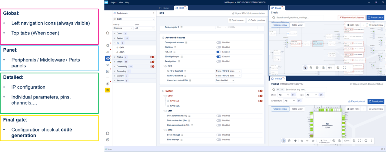
The error and conflict propagation mechanism is organized into four levels:
Global: Overall project status, visible in the main navigation area and in the currently opened workspaces.
Panel: Status of a panel, indicating which area of the project still contains issues.
Detailed: Status inside a specific configuration screen, pointing to the affected configuration or parameter.
Final gate: Overall configuration check performed at code generation time.
Global indicators 
Top tabs 
The top tabs show the status of each open workspace see (2) in Global indicators in STM32CubeMX2: left navigation bar and workspace tabs (for example, Pinout , Clock , Project Settings , FreeRTOS , DMA , NVIC , EXTI , IP configuration tabs).
Each tab can display a red or orange dot:
The presence of a dot indicates that at least one error or warning remains in that workspace.
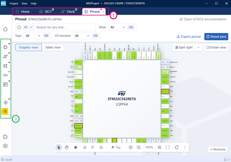
Global indicators in STM32CubeMX2: left navigation bar and workspace tabs 
Panel-level indicators 
Peripherals, middleware, and parts panels 
In the Peripherals , Middleware , and Parts panels, error indicators are shown at two levels.
- IP / Middleware / Part level: see (1) in Panel-level indicators: category badges and IP-level error icons
A red error icon or badge is displayed when the corresponding IP has configuration issues.
This tells the user which peripheral or component should be opened next to investigate the error.
- Category level: see (2) in Panel-level indicators: category badges and IP-level error icons
A red badge with a number indicates how many IPs in this category contain errors.
This allows users to quickly identify which subsystem concentrates the issues.
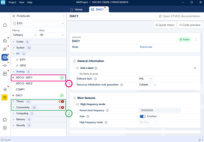
Panel-level indicators: category badges and IP-level error icons 
Detailed indicators 
Clock and pinout overview 
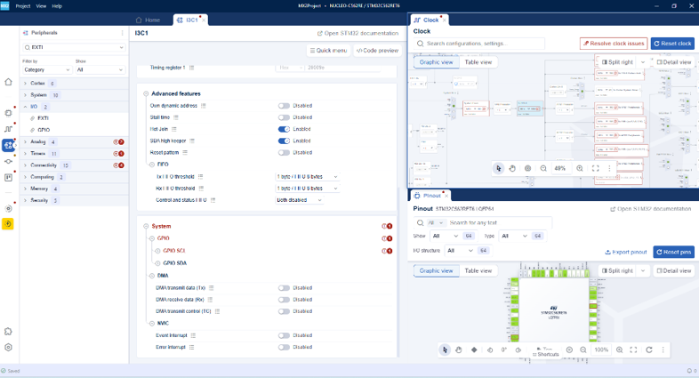
In complex projects, multiple areas can report issues at the same time. For example, clock configuration, peripheral configuration, and pinout conflicts. STM32CubeMX2 displays these issues in a unified workspace.
In this view:
The Peripherals panel shows which peripherals and categories contain errors or warnings.
The Clock view highlights clock configuration problems and provides tools to resolve them.
The Pinout view indicates pins in conflict or incorrectly assigned.
Linked views for the same issue 
A single configuration problem is propagated across all related views so that users can identify it from different entry points.
Examples include:
- System / GPIO conflicts:
Visible in the IP configuration (GPIO section).
Visible in the Pinout view, where the affected pin is highlighted with a red border.
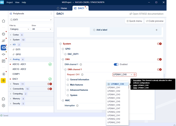
- DMA channel conflicts:
Visible in the peripheral configuration (DMA section).
Visible in the DMA view, where the corresponding channel row is marked as a conflict.
- EXTI line conflicts:
Visible in the IP configuration (EXTI section).
Visible in the EXTI view, where the corresponding line is flagged in red.
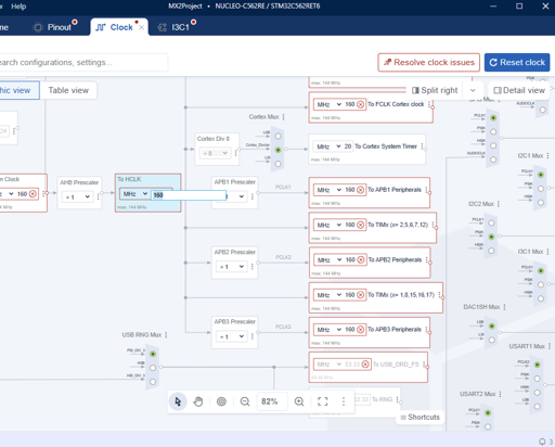
Clock conflict example 
When there is a clock configuration issue:
The clock elements affected by the issue are framed in red and marked with an error icon.
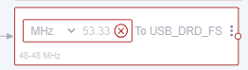
A dedicated button indicates the global status of the clock configuration:
Resolve clock issues: At least one clock error is present in the tree.

No clock issues: All clock issues have been resolved and no clock element is bordered in red.

Users have two options to correct these issues:
Click Resolve clock issues to allow STM32CubeMX2 automatically propose valid clock settings.
Locate the red elements in the clock tree and adjust the configuration manually.
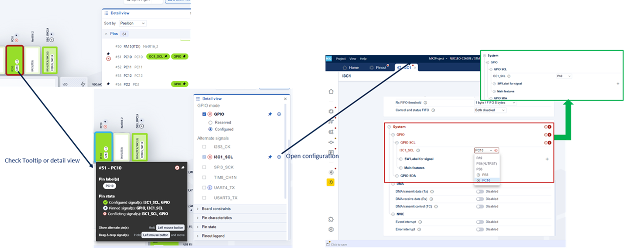
Pinout conflict example 
In the Pinout view :
Pins that have issues are highlighted directly on the package.
Users can hover over the pin or open the detail view to see which signals are in conflict.
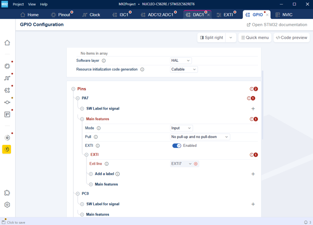
In the System → GPIO configuration:
- The pin selector uses icons to represent the pin status:
No icon: The pin is free (no signal mapped).
xicon: Indicates a conflict on that pin.!icon: Indicates that a signal is already mapped on that pin, but:This signal can be moved, and
The newly selected signal can be mapped to this pin.
To resolve the conflict, users must choose the appropriate pin and adjust the configuration.
DMA conflict example 
In the DMA view :
The instance tab shows a red badge containing the number of errors. See (1) in HowTo_Err_Fig17
- The channel row in conflict is highlighted. See (2) in HowTo_Err_Fig17:
A red error icon.
The number of conflicting requests.
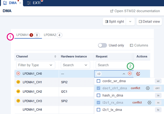
In the System → DMA configuration:
- The DMA channel selector uses icons to show the channel status:
No icon: The channel is free.
xicon: Indicates a conflict on that channel.
EXTI conflict example 
In the EXTI view :
Any EXTI line in conflict is marked in red. see (1) in HowTo_Err_Fig12
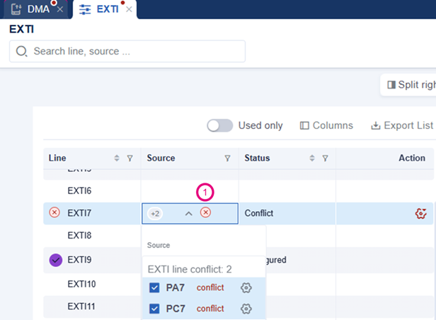
In the GPIO configuration :
The same issue is visible in the GPIO / EXTI settings of each pin.
The EXTI line associated with the conflict is highlighted as an error.
To solve the conflict, the user can disable EXTI on one of the pins sharing the same EXTI line.
Configuration check at code generation 
When code generation starts, STM32CubeMX2 performs a global configuration check on the entire project.

If any error or warning remains, a popup is displayed:
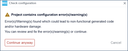
Impact of remaining errors and warnings 
If configurations are generated while errors or warnings are still present, the following issues may occur:
Nonfunctional generated code.
Potential hardware damage in extreme cases, depending on the configuration.
User options 
When the popup is displayed, users can:
Review and fix the reported issues, then start code generation again.
Click Continue anyway to proceed with code generation at their own risk.