
Pinout 
This interface allows users to configure and manage the microcontroller pin assignments and properties. The pinout view is available in two formats:
Graphic view: Displays the pinout in a graphical layout representing the physical package of the microcontroller, such as BGA or QFP (see Pinout - graphic view)).
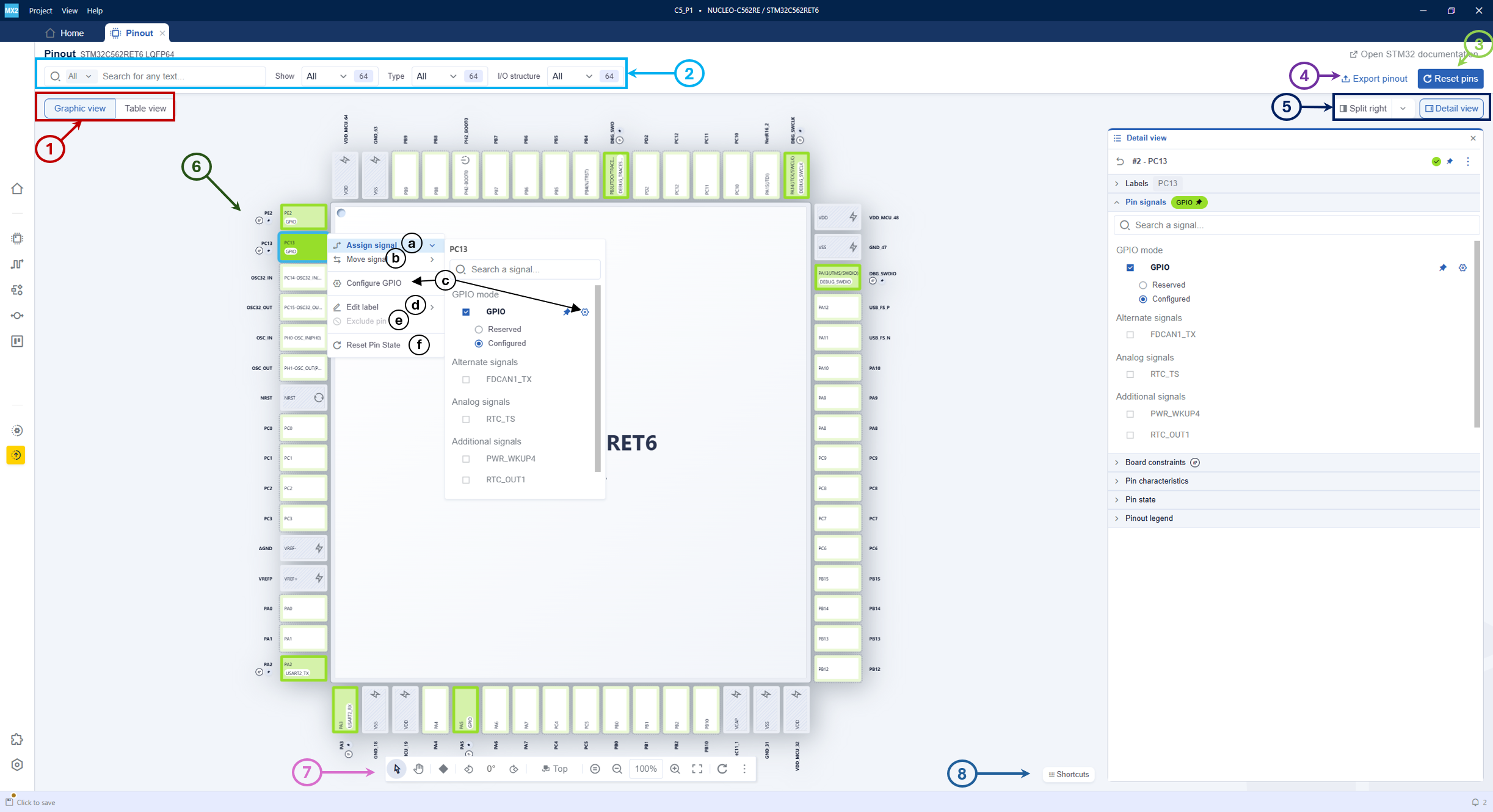
Pinout - graphic view 
Table view: Presents the pinout information in a tabular format for easier reading and editing (see Pinout - table view).
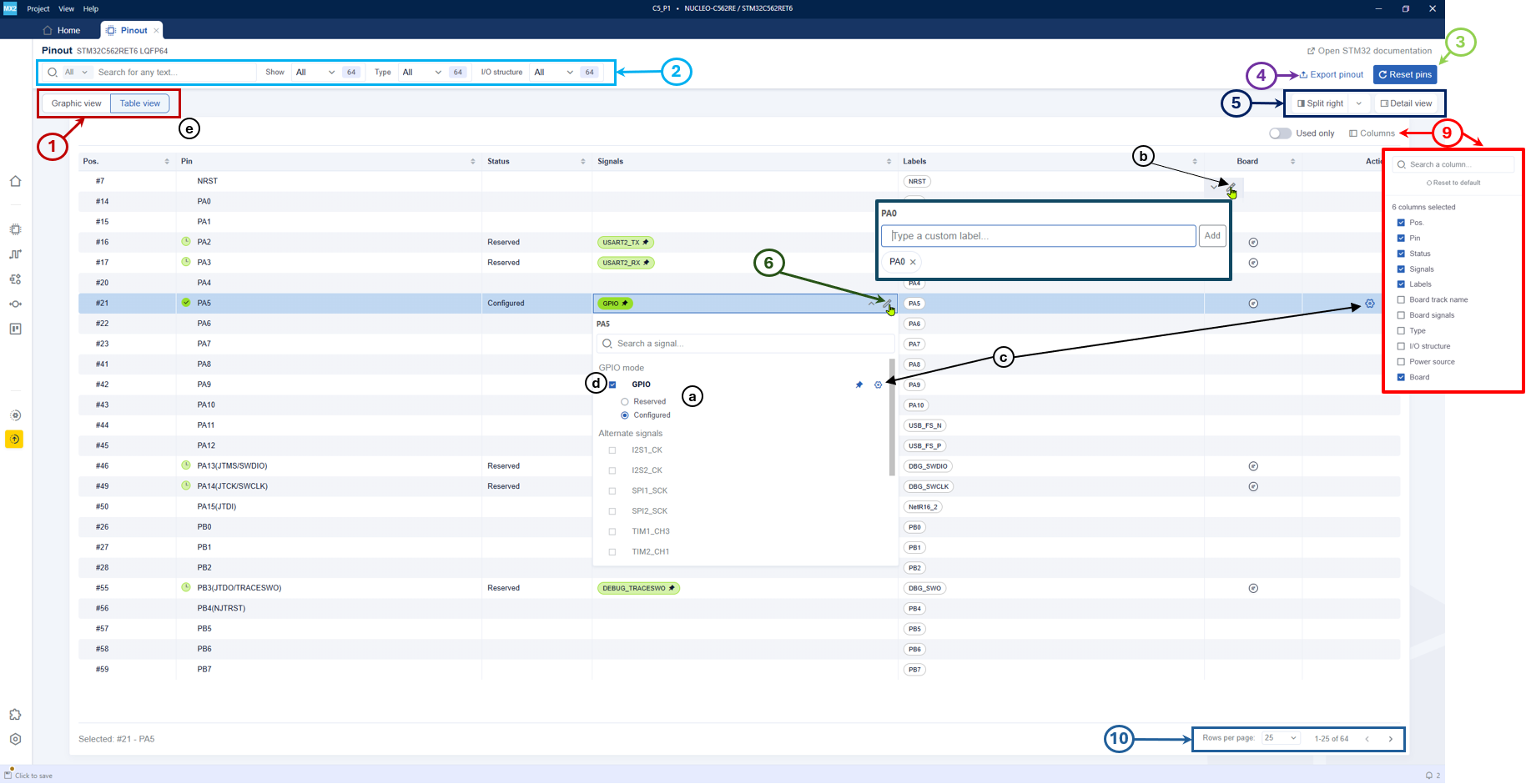
Pinout - table view 
In both views, users can perform the following actions:
Switch view (1): Switch between graphic and table views.
Search and filter options (2): Use dropdown menus to filter pins by type, function, I/O structure, or power.
- Reset pins (3): Reset the pinout configuration. This action:
Resets all reserved signals.
Preserves all configured signals except GPIO signals.
Preserves pin labels.
Restores excluded pins.
Export pinout (4): Export the pinout configuration to a CSV file.
Toggle detail view and split screen (5): Enable or disable the detail view panel on the right side of the interface (see Pinout - property view), and split the screen horizontally or vertically.
- Configure pinout (6): Includes the following options:
Assign signal (a): When clicked, a dropdown displaying available signals is presented. Navigate through this dropdown and choose the appropriate signal to link with the pin.
Move signal (b): When clicked, the user can move the signal to an alternate pin.
Go to configuration (c): It opens the software configuration in a new window.
Edit label (d): Assign a custom label to the pin.
Exclude pin (e): Clicking this option excludes the pin from the pinout configuration.
Reset pin state (f): Return the pin to unassigned state.
Note
When opening the graphic view, locate the desired pin for signal assignment. Right-click the pin to access the context menu.
- In STM32CubeMX2, signal allocation is distinct from configuration:
Reserved pins are used to ensure that all necessary signals can be mapped. This is mainly used by board designers, as they do not need the generated code.
Configured pins are used to generate code for GPIOs and for signals used by peripherals configured in the project.
- The following functionalities are only available in the graphic view (see Pinout - graphic view):
-
Navigation and zoom controls (7): The bottom toolbar provides tools for zooming and package orientation. (See Pinout - graphic view toolbar).
Keyboard shortcuts (8): Access a list of available shortcuts to speed up operations within the graphic view. (See Pinout - graphic view shortcuts).
- The following functionalities are only available in table view (See Pinout - table view):
-
Columns table settings (9): Customize the columns displayed in the table view by enabling or disabling specific columns.
Pagination controls (10): Navigate through different pages of the table view.
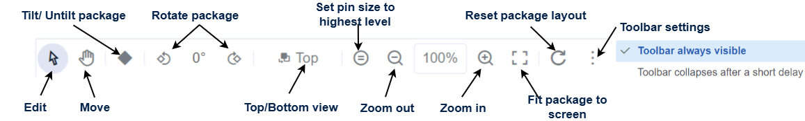
Pinout - graphic view toolbar 
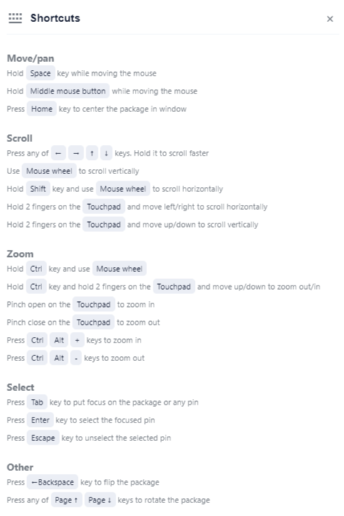
Pinout - graphic view shortcuts 
Note
The Tilt/Untilt package option is only available for QFP and QFN packages.
The detail view serves three main roles in the pinout view:
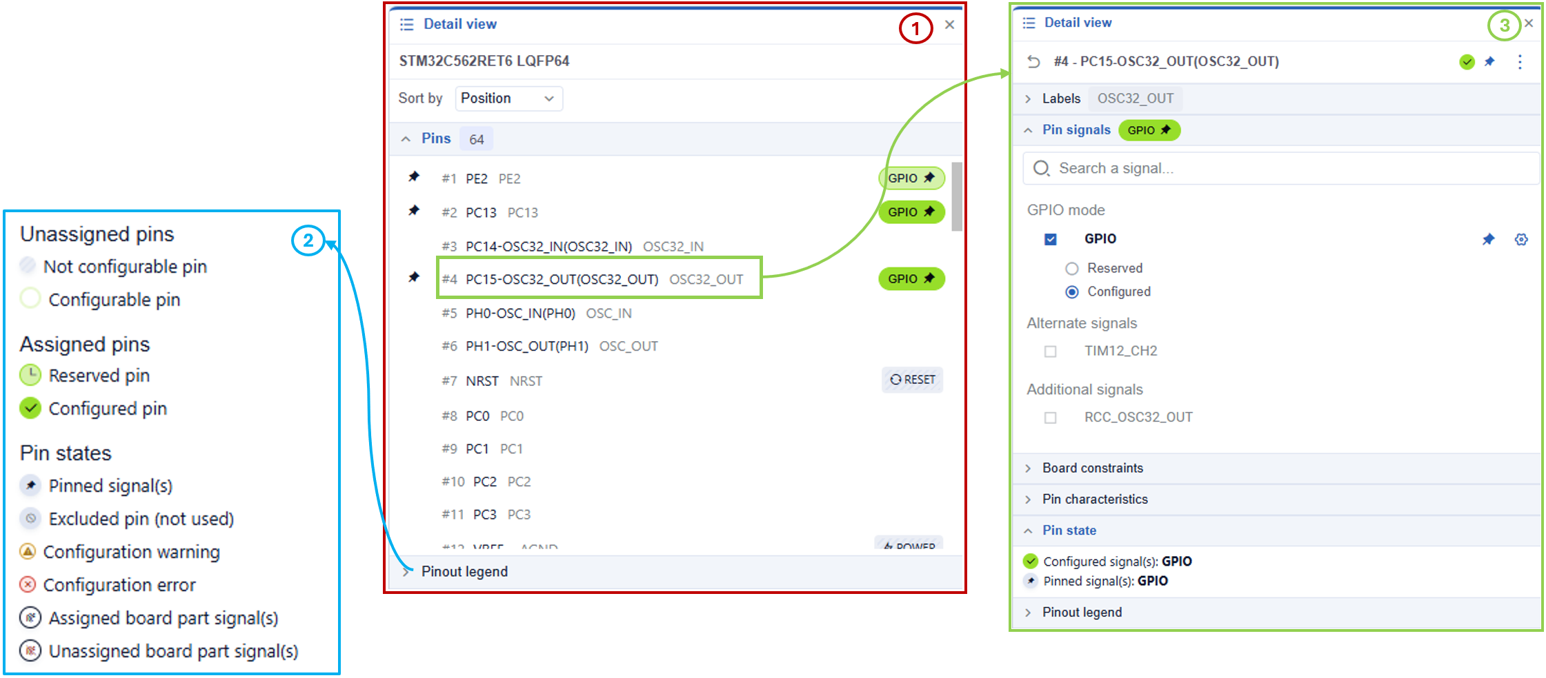
Pinout - property view 
Pins (1): List all pins for the selected microcontroller and allow selection of a single pin.
Pinout legend (2): Provide a detailed explanation of the color coding and icons used in the pinout graphic view.
- Details on selected pins (3): When a pin is selected, the detail view displays information about its configuration and characteristics, including:
Labels: Add labels to the selected pin.
Pin signals: Perform all actions described in point 6: configure pinout, such as assigning signals, adding or removing pin labels, and resetting pin states.
Board constraints (only if the project was created from a board): Display constraints such as the track name.
Pin characteristics: Show details such as input/output type and voltage supply.
Pin state: It shows the current state of the pin.
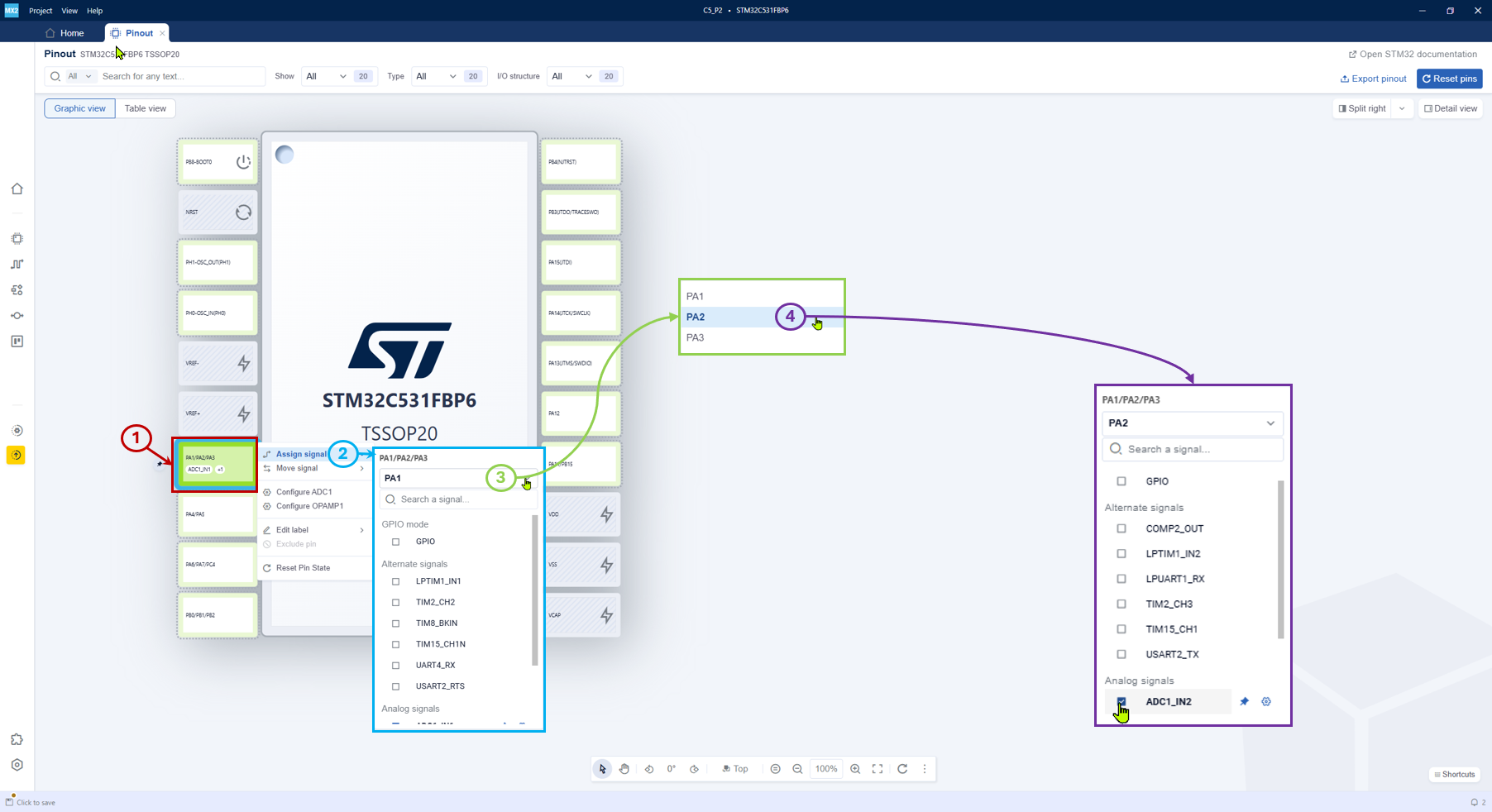
Pinout multibonding 
Multibonding refers to the configuration where multiple MCU pads share the same physical pin on a package. This feature is particularly relevant for packages with low pin count, as it allows efficient pin multiplexing to optimize limited pin availability in these compact packages.
Pinout multibonding 
- To configure multibonding in STM32CubeMX2, follow these steps:
-
Select the pin (1): Click the desired pin (for example, PA1/PA2/PA3).
Open assign signal menu (2): Choose Assign signal.
Select the bonded pin (3): From the list, select the desired pin (PA2).
View signals for PA2 (4): Pick the required signal from the list and switch between options (for example, ADC1-IN2). You can select signals only on one pin.
Pinout Conflicts 
When the same pin is used for different functions, a pinout conflict arises. STM32CubeMX2 shows conflicts directly in the pinout or table view using visual indicators (for example, color coding or icons) to highlight the conflicting pins. To resolve pinout conflicts, users can take the following steps: - Identify conflicting pins: Look for visual indicators in the pinout view that highlight pins with conflicts.
Review peripheral configurations: Check the configurations of the peripherals associated with the conflicting pins to understand their requirements.
Reassign pins: Use the pinout view to reassign one or more of the conflicting pins to alternative available pins that do not have conflicts.
Validate changes: After reassigning pins, validate the changes to ensure that the conflicts have been resolved and that all peripherals are correctly configured.