
 STM32CubeProgrammer

CAN connection 
Introduction 
This is the first panel to look at before connecting to a target. It allows the user to select the target interface (either the debug interface using ST-LINK/J-Link debug probe, or the bootloader interface over UART, USB, SPI, CAN, or I2C).
CAN settings 
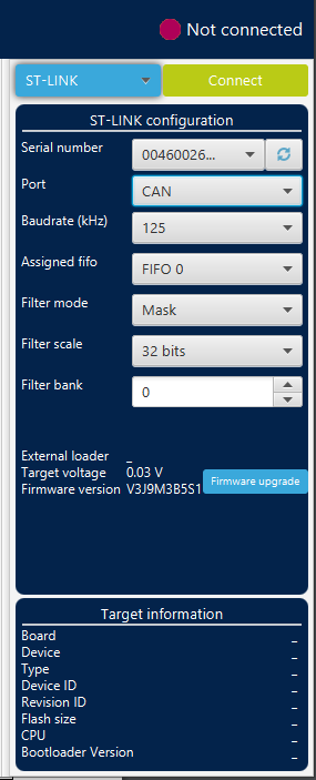
Fig. 168 CAN configuration panel 
CAN bootloader fields 
Serial number: this field contains the serial numbers of all connected ST-LINK-V3 probes in case to use CAN bootloader.
Port: selects the CAN devices connected to the PC. You can use the refresh button to recheck the available devices.
Baudrate: selects the CAN baud rate.
Assigned FIFO: selects the receive FIFO memory to store incoming messages.
Filter mode: selects the type of the filter, MASK, or LIST.
Filter scale: selects the width of the filter bank, 16 or 32 bits.
Filter bank: values between 0 and 13, to choose the filter bank number.
Connect command (-c, –connect) 
- Description:
-
Establishes the connection to the device. This command allows the host to open the chosen device port (UART/USB/JTAG/SWD/JLINK/SPI/CAN/I2C).
Syntax:
-c port=<Portname> [noinit=<noinit_bit>] [options]
- port=<Portname>
-
Interface identifier, for example COMx (for Windows), /dev/ttySx (for Linux), usbx for USB interface, and SPI, I2C, or CAN for the corresponding SPI, I2C, and CAN interfaces.
- [noinit=<noinit_bit>]
-
Set No Init bits, value in {0, 1}, default 0. noinit=1 can be used if a previous connection is active.
CAN options 
[br=<rbaudrate>] Baudrate: 125, 250…, default 125.
[mode=<canmode>] Mode: NORMAL, LOOPBACK…, default NORMAL.
[ide=<type>] Type: STANDARD or EXTENDED, default STANDARD.
[rtr=<format>] Frame format: DATA or REMOTE, default DATA.
[fifo=<afifo>] Assigned FIFO: FIFO0 or FIFO1, default FIFO0.
[fm=<fmode>] Filter mode: MASK or LIST, default MASK.
[fs=<fscale>] Filter scale: 16 or 32, default 32.
[fe=<fenable>] Activation: ENABLE or DISABLE, default ENABLE.
[fbn=<fbanknb>] Filter bank number: 0 to 13, default 0.
- Note:
-
The software must request the hardware to enter Normal mode to synchronize on the CAN bus and start reception and transmission between the Host and the CAN device. Normal mode is recommended.