
 STM32CubeProgrammer

SPI connection 
Introduction 
Target configuration panel 
This is the first panel to look at before connecting to a target. It allows the user to select the target interface (either the debug interface using ST-LINK/J-Link debug probe, or the bootloader interface over UART, USB, SPI, CAN, or I2C).
SPI settings 
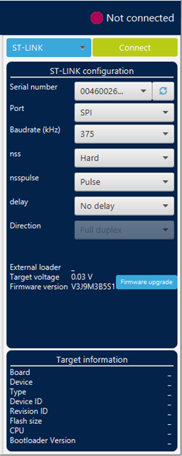
Fig. 167 SPI configuration panel 
SPI bootloader fields 
Serial number: this field contains the serial numbers of all connected ST-LINK-V3 probes in case of use of SPI bootloader.
Port: selects the SPI devices connected to the PC. Use the refresh button to recheck the available devices.
Baudrate: selects the SPI baud rate.
nss: slave select software or hardware.
nsspulse: the slave selection signal can operate in a pulse mode, where the master generates pulses on nss output signal between data frames for a duration of one SPI clock period when there is a continuous transfer period.
Delay: used to insert a delay of several microseconds between data.
Direction: must be always Full-duplex, both data lines are used, and synchronous data flows in both directions.
Connect command (-c, –connect) 
- Description:
-
Establishes the connection to the device. This command allows the host to open the chosen device port (UART/USB/JTAG/SWD/JLINK/SPI/CAN/I2C).
Syntax:
-c port=<Portname> [noinit=<noinit_bit>] [options]
- port=<Portname>
-
Interface identifier, for example COMx (for Windows), /dev/ttySx (for Linux), usbx for USB interface, and SPI, I2C, or CAN for the corresponding SPI, I2C, and CAN interfaces.
- [noinit=<noinit_bit>]
-
Set No Init bits, value in {0, 1}, default 0. noinit=1 can be used if a previous connection is active.
SPI options 
[br=<baudrate>]
[cpha=<cpha_val>]
[cpol=<cpol_val>]
[crc=<crc_val>]
[crcpol=<crc_pol>]
[datasize=<size>]
[direction=<val>]
[firstbit=<val>]
[frameformat=<val>]
[mode=<val>]
[nss=<val>]
[nsspulse=<val>]
[delay=<val>]
- Note:
-
Baudrate (for example 187, 375, 750), default 375.
To use SPI on high speed, an infrastructure hardware must be respected to ensure the proper connection on the bus.
Option values and defaults:
CRC polynomial value.
8- or 16-bit, default 8-bit.
2LFullDuplex/2LRxOnly/1LRx/1LTx.
MSB/LSB, default MSB.
Motorola/TI, default Motorola.
Master/slave, default master.
Soft/hard, default hard.
Pulse/NoPulse, default Pulse.
Delay/NoDelay, default Delay.