
 STM32CubeProgrammer

MCU command lines 
Generic commands 
This section presents the set of commands supported by all STM32 MCUs.
|
Long Command |
Short Command |
Description |
|---|---|---|
|
-c |
Establishes the connection to the device. This command allows the host to open the selected device port (UART/USB/JTAG/SWD/J-LINK/SPI/CAN/I2C). |
|
|
-e |
According to the given arguments, this command can be used to erase specific sectors or the whole flash memory. This operation can take a second or more to complete, depending on the involved size. |
|
|
-d, -w |
Downloads the content of the specified binary file into the memory of the device. The download operation is preceded by the erase operation. A write address is needed to download binary files. |
|
|
-v, -v fast |
Used for validation of data integrity with two mechanisms: legacy uses a bit-by-bit comparison, while fast uses a sector-by-sector comparison. If the device does not support checksums, the legacy mechanism is used instead. |
|
|
-w32 |
Downloads the specified 32-bit data into flash memory starting from a specified address. |
|
|
-r, -u |
Reads and uploads the device memory content into a specified binary file starting from a specified address. |
|
|
-g, -s |
This command enables execution of the device memory starting from the specified address. |
|
|
-rst |
Executes a software system reset. |
|
|
-hardRst |
Generates a hardware reset through the RESET pin in the debug connector. The RESET pin of the JTAG connector (pin 15) must be connected to the device reset pin. |
|
|
-pwr |
Controls the target board power through an ST-LINK probe that supports this capability. The command can be used even without the -c connect command. |
|
|
-halt |
Halts the core. |
|
|
-step |
Executes one instruction. |
|
|
-score |
Displays the Cortex-M core status. The core status can be one of the following: ”Running”, ”Halted”, ”Locked up”, ”Reset”, ”Locked up” or ”Kept under reset” |
|
|
-coreReg |
Read/write Cortex-M core registers. The core is halted before a read/write operation. |
|
|
-l |
This command lists all available UART, DFU and STLink interfaces. |
|
|
-getTargetSelList |
Lists all the devices currently connected via ST-LINK on the same SWD bus supporting the SWD multidrop. |
|
|
-q |
This command disables the progress bar display during download and read commands |
|
|
-rstbl |
Enables a reset function compatible with all bootloader interfaces. The connection must be established while performing the operation. |
|
|
-vb |
This command makes it possible to display more messages, to be more verbose. |
|
|
–log |
This traceability command makes it possible to store the whole traffic (with maximum verbosity level) into a log file. |
|
|
-el |
This command allows entering the path of one or more external memory loaders to perform programming, write, erase, and read operations with an external memory. |
|
|
-elbl |
With this command, the user can provide the path of an external memory loader used to perform programming, write, erase, and read operations using bootloader interfaces. |
|
|
-rdu |
This command removes the memory read protection by changing the RDP level from level 1 to level 0. |
|
|
-tzenreg |
This command removes TrustZone protection by disabling TZEN from 1 to 0. |
|
|
-ob |
This command allows the user to manipulate the device option bytes by displaying or modifying them. |
|
|
-sl |
This command allows a firmware file to be modified by adding a load area (segment) containing the computed CRC values of the user program. |
|
|
-sfi |
Programs an sfi file. |
|
|
-rsse |
This command allows the user to select the root secure services extension library (RSSe). |
|
|
-a |
This command allows the user to clean a not properly finished process. The currently ongoing operation stops and the system returns to idle state. |
|
|
-mcsv |
This command allows the user to select the modules file including the list of modules to be installed with SFI. This option is mandatory when the SFI image integrates at least one module (area of type m). |
|
|
-sfi |
Programs an sfix file |
|
|
-rsse |
This command allows the user to select the root secure services extension library (RSSe). Mandatory for devices using RSSe to make secure firmware install (SFI). The RSSe binary file can be found in STM32CubeProgrammer bin/RSSe folder. |
|
|
-a |
This command allows the user to clean a not properly finished process. The ongoing operation stops and the system returns to idle state. |
|
|
-mcsv |
This command allows the user to select the modules file including the list of modules to be installed with SFI. This option is mandatory when the SFI image integrates at least one module (area of type m). |
|
|
-ecsv |
This command is used for Secure Manager Secure Modules install in external flash. It allows the user to select the modules file including the list of external modules to be installed with SFIx. This option is mandatory when the SFI image integrates at least one external module (area of type e). |
|
|
-hsmgetinfo |
Reads the HSM available information. |
|
|
-hsmgetcounter |
Reads the current value of the license counter. |
|
|
-hsmgetfwid |
Reads the Firmware/Module identifier. |
|
|
-hsmgetstatus |
Reads the current card life-cycle state. |
|
|
-hsmgetlicense |
Gets a license for the current chip if counter is not null. |
|
|
-hsmglfcb |
Gets a license for the current certificate binary file if counter is not null. |
|
|
-antirollback |
Perform the antirollback operation. |
|
|
-startfus |
Start the FUS. |
|
|
-getuid64 |
Read the device unique identifier (UID). |
|
|
-fusgetstate |
Read the FUS state. |
|
|
-fwdelete |
Delete the BLE stack firmware. |
|
|
-fwupgrade |
Upgrade of BLE stack firmware or FUS firmware. |
|
|
-startwirelessstack |
Start the wireless stack. |
|
|
-authkeyupdate |
Authentication key update. |
|
|
-authkeylock |
Authentication key lock. |
|
|
-wusrkey |
Write user key. |
|
|
-swv |
Accesses serial wire viewer console mode. |
|
|
-startswv |
Accesses serial wire viewer console mode. |
|
|
-dsecurity |
Disables security on STM32WL. |
|
|
-setdefaultob |
Configures option bytes to their default values on STM32WL. |
|
|
-ob unlockchip |
Unlocks STM32WL when bad option bytes are programmed. |
|
|
-ssigfoxc |
Saves the SigFox chip certificate to a binary file. |
|
|
-wsigfoxc |
Writes the SigFox chip certificate. |
|
|
-regdump |
Reads and dumps core and MCU registers. |
|
|
-hf |
Starts hard fault analysis. |
|
|
-fchecksum |
Calculates the checksum value for the entire file content. |
|
|
-checksum |
Calculates the checksum value for accessible memory. |
|
|
-lockRDP1, -setOEM1KEY |
Locks RDP regression from level 1 with a password. |
|
|
-lockRDP2, -setOEM2KEY |
Locks RDP regression from level 2 with a password. |
|
|
-unlockRDP1 |
Unlocks RDP regression from level 1 with a password. |
|
|
-unlockRDP2 |
Unlocks RDP regression from level 2 with a password. |
|
|
-lockbs |
Provisions the boundary-scan key. |
|
|
-unlockbs |
Performs the boundary-scan RDP transition. |
|
|
-gc |
Reads the chip certificate. |
|
|
-w32dbgmcu |
Writes 32-bit data to the DBGMCU AUTH HOST register. |
|
|
-sdp |
Programs OBKey content. |
|
|
-pwd |
Provisions a password and generates a password.bin file. |
|
|
debugauth |
Performs debug-auth discovery, authentication, or debug close, posssible value: 1|2|3. |
|
|
–force_no_da |
Forces product-state OB programming without configured debug authentication. |
|
|
-installipmodule |
Installs a Secure Manager IP module. |
|
|
-updateipmodule |
Updates a Secure Manager IP module. |
|
|
–skiperase |
Skips sector erase before programming. |
|
|
-storekeyotp |
Stores an authentication public key in OTP. |
|
|
-rssekw |
Selects RSSeKW and executes private-key wrapping. |
|
|
-r32fast |
Fast read 32-bit data memory. |
|
|
-y |
Confirms STM32V8 programming when the tool blocks the risky operation. |
|
|
-blankcheck |
Verifies that the STM32 flash memory is blank. If this is not the case, the first address containing data is highlighted in a message. |
|
|
-fillmemory |
This command allows the user to fill memory with a given pattern from the chosen address. |
Command details 
-connect 
Syntax:
-c


             port=<Portname>


             [noinit=<noinit_bit>]


             [options]
port=<Portname>: Interface identifier, for example
COMx
(for Windows),
/dev/ttySx
(for Linux),
usbx
for USB interface,
SPI,
I2C
and
CAN
for, respectively, SPI, I2C and CAN interfaces.
[noinit=<noinit_bit>]: Set No Init bit, value in {0, 1}, default is 0.
noinit=1
can be used if a previous connection is active.
ST-LINK options
|
Option |
Description |
|---|---|
|
[freq=<frequency>] |
Frequency (in kHz) used for the connection. Default value is 4000 kHz for SWD port, and 9000 kHz for JTAG port. |
|
[reset=<mode>] |
Reset mode. Possible values are {SWrst/HWrst/Crst}. The default
value is
|
|
[HWrst] |
Hardware reset. Performed by the ST-LINK, which physically drives the NRST pin of the MCU. The NRST pin of the ST-LINK must be connected to the MCU. |
|
[SWrst] |
Software reset (a system reset via Cortex registers). |
|
[Crst] |
Core reset (via Cortex registers). |
|
[index=<index>] |
Index of the debug probe. Default index value is 0. |
|
[sn=<serialNumber>] |
Serial number of the debug probe. Use this option if you need to connect to
a specific ST-LINK probe for which you know the serial number. Do not use this
option together with the
|
|
[mode=<mode>] |
Connection mode. Value in {NORMAL/UR/HOTPLUG}. Default value is
|
|
[NORMAL] |
With
|
|
[UR] |
The Connect Under Reset mode enables connection to the target using a reset vector catch before executing any instruction. This is useful, for example, when the target contains code that disables the JTAG/SWD pins. |
|
[HOTPLUG] |
The Hot Plug mode enables connection to the target without a halt or reset. This is useful for updating the RAM addresses or the IP registers while the application is running. |
|
[POWERDOWN] |
Allows putting the target in debug mode, even if the application has not started since the target power-up. The hardware reset signal must be connected between ST-LINK and the target. This feature might not be fully effective on some boards (MB1360, MB1319, MB1361, MB1355) with the STMPS2141 power switch. |
|
[hwRstPulse] |
The tool generates a reset pulse and then connects to the target. This connection mode does not prevent application launch before connection. It is used on devices where under-reset mode is not available, such as STM32WB0x and STM32WL33. |
|
[ap=<accessPort>] |
Access port index. Default access port value is 0. |
|
[speed=<speed_mode>] |
Connection speed. Default is
|
|
[Reliable] |
Allows the user to connect in slow mode. |
|
[Fast] |
Allows the user to connect in fast mode. |
|
[shared] |
Enables shared mode, allowing connection of two or more instances of STM32CubeProgrammer or other debuggers to the same ST-LINK probe. |
|
[tcpport=<Port>] |
Selects the TCP port to connect to an ST-LINK server. The
|
|
[dLPM / LPM] |
Disable/enable debug in low-power mode (default configuration is enabled for the supported devices (STM32U5/WB/L4 series)). |
|
[getAuthID] |
Get device identification (only for STM32U5 series). This is a 32-bit device-specific quantity that can be read through the JTAG port. This 32-bit information is used to derive the expected OEM password keys to unlock this specific device. This command is not applicable when RDP level = 0 (MCU constraint). |
Note
Shared mode is supported only on Windows.
USB options: the connection under the DFU interface supports two options, namely product and vendor IDs (default values PID = 0xDF11, VID = 0x0483).
SPI options
|
Option |
Description |
|---|---|
|
[br=<baudrate>] |
Baudrate (for example 187, 375, 750). Default is 375. |
|
[cpha=<cpha_val>] |
1Edge or 2Edge. Default is 1Edge. |
|
[cpol=<cpol_val>] |
Low or High. Default is Low. |
|
[crc=<crc_val>] |
Enable or disable (0/1). Default is 0. |
|
[crcpol=<crc_pol>] |
CRC polynomial value. |
|
[datasize=<size>] |
8- or 16-bit. Default is 8-bit. |
|
[direction=<val>] |
2LFullDuplex / 2LRxOnly / 1LRx / 1LTx. |
|
[firstbit=<val>] |
MSB or LSB. Default is MSB. |
|
[frameformat=<val>] |
Motorola or TI. Default is Motorola. |
|
[mode=<val>] |
Master or Slave. Default is Master. |
|
[nss=<val>] |
Soft or Hard. Default is Hard. |
|
[nsspulse=<val>] |
Pulse or NoPulse. Default is Pulse. |
|
[delay=<val>] |
Delay/NoDelay, default Delay |
Note
To use SPI at high speed, the hardware infrastructure must comply with the requirements to ensure proper connection on the bus.
Direct GPIO bootloader programming on Raspberry Pi:
This mode programs an STM32 target from a Raspberry Pi or compatible ARM Linux host without ST-LINK V3. The STM32 target must already be in bootloader mode.
SPI direct GPIO command
SPI prerequisites:
Enable SPI on the Linux host.
Check nodes with:
ls /dev/spidev*Connect NSS, SCK, MISO, MOSI, and GND.
STM32_Programmer_CLI -c port=spidevX.X -d "firmware.bin" "<start_address>"
Example:
STM32_Programmer_CLI -c port=spidev0.0 -d "application.bin" 0x08000000
J-Link options
|
Option |
Description |
|---|---|
|
[reset=<mode>] |
Reset mode. Possible values are {SWrst/HWrst/Crst}. The default value is SWrst. When using UR connection mode, the reset mode is HWrst. |
|
[HWrst] |
Hardware reset. Performed by the STLink, which physically drives the NRST pin of the MCU. The NRST pin of the STLink must be connected to the MCU. |
|
[SWrst] |
Software reset (a system reset via Cortex registers) |
|
[Crst] |
Core reset (via Cortex registers) |
|
[sn=<serialNumber>] |
Serial number of the debug probe. Use this option if you need to connect to a specific ST-LINK probe of which you know the serial number. |
|
[mode=<mode>] |
Connection mode. Value in {NORMAL/UR/HOTPLUG}. Default value is NORMAL. |
|
[Normal] |
With “Normal” connection mode, the target is reset, then halted. The type of reset is selected using the “Reset Mode” option. |
|
[UR] |
The “Connect Under Reset” mode enables connection to the target using a reset vector catch before executing any instructions. This is useful in many cases, for example when the target contains a code that disables the JTAG/SWD pins. |
|
HOTPLUG |
The “Hot Plug” mode enables connection to the target without a halt or reset. This is useful for updating the RAM addresses or the IP registers while the application is running. |
|
[ap=<accessPort>] |
Access port index. Default access port value is 0. |
|
[speed=] |
Connection speed. Default is Reliable. Available only for Cortex-M33. |
|
Reliable |
Allows the user to connect with a slow mode. |
|
Fast |
Allows the user to connect with a fast mode. |
I2C options
|
Option |
Description |
|---|---|
|
[add=<ownadd>] |
Slave address: address in hex format |
|
[br=<sbaudrate>] |
Baudrate: 100 or 400 kbps, default 400 kbps. |
|
[sm=<smode>] |
Speed Mode, STANDARD or FAST, default FAST. |
|
[am=<addmode>] |
Address Mode: 7 or 10 bits, default 7. |
|
[af=<afilter>] |
Analog filter: ENABLE or DISABLE, default ENABLE. |
|
[df=<dfilter>] |
Digital filter: ENABLE or DISABLE, default DISABLE. |
|
[dnf=<dnfilter>] |
Digital noise filter: 0 to 15, default 0. |
|
[rt=<rtime>] |
Rise time: 0-1000 (STANDARD), 0-300 (FAST), default 0. |
|
[ft=<ftime>] |
Fall time: 0-300 (STANDARD), 0-300 (FAST), default 0. |
Note
I2C address option must be always inserted, otherwise the connection is not established.
CAN options
|
Option |
Description |
|---|---|
|
[br=<rbaudrate>] |
Baudrate: 125, 250…, default 125. |
|
[mode=<canmode>] |
Mode: NORMAL, LOOPBACK…, default NORMAL. |
Note
The software must request the hardware to enter Normal mode to synchronize on the CAN bus and start reception and transmission between the Host and the CAN device. Normal mode is recommended.
|
Option |
Description |
|---|---|
|
[ide=<type>] |
Type: STANDARD or EXTENDED, default STANDARD. |
|
[rtr=<format>] |
Frame format: DATA or REMOTE, default DATA. |
|
[fifo=<afifo>] |
Assigned FIFO: FIFO0 or FIFO1, default FIFO0. |
|
[fm=<fmode>] |
Filter mode: MASK or LIST, default MASK. |
|
[fs=<fscale>] |
Filter scale: 16 or 32, default 32. |
|
[fe=<fenable>] |
Activation: ENABLE or DISABLE, default ENABLE. |
|
[fbn=<fbanknb>] |
Filter bank number: 0 to 13, default 0. |
Using UART
./STM32_Programmer.sh -c port=/dev/ttyS0 br=115200
The result of this example is shown in the following figure.
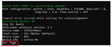
Fig. 102 Connect operation using RS232 
STM32CubeProgrammer provides the possibility to configure RTS and DTR pins:
RTS, used as follows:
rts=lowDTR, used as follows:
dtr=high
Example:
STM32_Programmer_CLI.exe -c port=COM27 dtr=high

Fig. 103 Enabling COM DTR pin 
Example using USB
./STM32_Programmer.sh -c port=usb1
The result of this example is shown in the following figure.
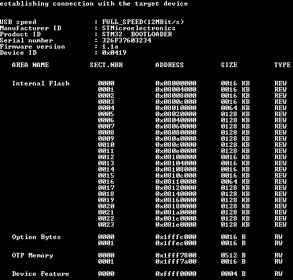
Fig. 104 Connect operation using USB 
Note
When using a USB interface, all the configuration parameters such as baudrate, parity, data-bits, frequency, and index are ignored. To connect using a UART interface, the port configuration baudrate, parity, data-bits, stop bits, and flow-control must have a valid combination depending on the used device.
Example using DFU IAP/USBx options
./STM32_Programmer.sh -c port=usb1 pid=0xA38F vid=0x0438
The result of this example is shown in the following figure.
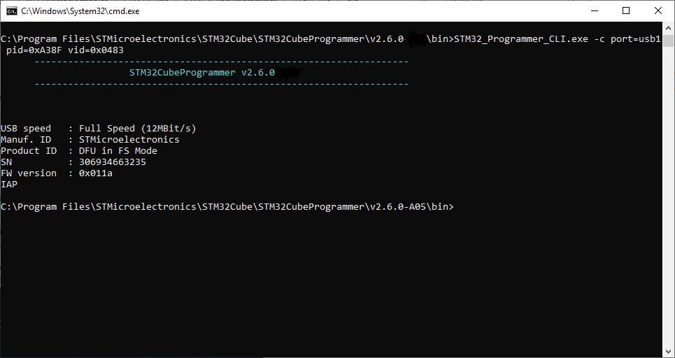
Fig. 105 Connect operation using USB DFU options 
Note
The default product ID and vendor ID values are ST product values: PID = 0xDF11 and VID = 0x0483.
Example using JTAG/SWD debug port
To connect using port connection mode with an ST-LINK probe, it is necessary to mention the port name with at least the connect command, for example:
-c port=JTAG
Note
Make sure that the device being used contains a JTAG debug port when trying to connect through JTAG.
There are other parameters used in connection with JTAG/SWD debug ports that have default values. See the tool help for more information about those default values.
The example below shows a connection example with an STM32 with device ID 0x415.
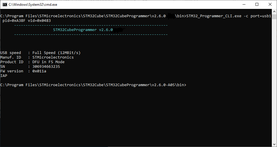
Fig. 106 Connect operation using SWD debug port 
The corresponding command line for this example is
-c


             port=SWD


             freq=3900


             ap=0
.
In the connect command (
-c


             port=SWD


             freq=3900


             ap=0
):
The
portparameter is mandatory.The index is not mentioned in the command line. The
indexparameter takes the default value 0.The frequency entered is 3900 kHz; however, the connection is established at 4000 kHz. This is because the ST-LINK probe has fixed values with SWD and JTAG debug ports.
ST-LINK V2/V2.1:
SWD: 4000, 1800, 950, 480, 240, 125, 100, 50, 25, 15, and 5 kHz
JTAG: 9000, 4500, 2250, 1125, 562, 281, and 140 kHz
ST-LINK V3:
SWD: 24000, 8000, 3300, 1000, 200, 50, and 5 kHz
JTAG: 21333, 16000, 12000, 8000, 1777, and 750 kHz
If the value entered does not correspond to one of these values, the next highest one is considered. Default frequency values are:
SWD: ST-LINK V2: 4000 kHz, ST-LINK V3: 24000 kHz
JTAG: ST-LINK V2: 9000 kHz, ST-LINK V3: 21333 kHz
Note
JTAG frequency selection is supported only with ST-LINK firmware versions from V2J23 onward.
To connect to access port 0, the
ap
parameter is used in this example, so any
command used after the connect command is established through the selected access port.
The ST-LINK probe firmware version is shown when connecting to the device. Make sure that you have the latest version of ST-LINK firmware V2J28M17 (STSW-LINK007), available on www.st.com.
Example using J-Link debug port
To connect using port connection mode with a J-Link probe, it is necessary to mention the port name with at least the connect command, for example:
-c port=JLINK
Only Flash and Option Bytes (OB) programming are supported via J-Link. Other features are not supported.
Note
There are other parameters used in connection with the J-Link debug port that have default values. See the tool help for more information about those default values.
The example below shows a connection example with an STM32 with device ID 0x480.

Fig. 107 Connect operation using J-Link debug port 
The corresponding command line for this example is
-c


             port=JLINK


             ap=0
.
In the connect command (
-c


             port=JLINK


             ap=0
):
The
portparameter is mandatory.The default frequency value is 4000.
Note
To connect to access port 0, the
ap
parameter is used in this example, so any command used after the connect command is established through the selected access port.
Example using SPI
STM32_Programmer_CLI -c port=SPI br=375 cpha=1edge cpol=low
The result of this example is shown in the following figure.
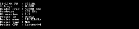
Fig. 108 Connect operation using SPI port 
Note
Make sure that the used device supports a SPI bootloader when trying to connect through SPI.
There are other parameters used in connection with the SPI port that have default values, and some others must have specific values. See the tool help for more information.
Example using CAN
STM32_Programmer_CLI -c port=CAN br=125 fifo=fifo0 fm=mask fs=32 fe=enable fbn=2
The result of this example is shown in the following figure.
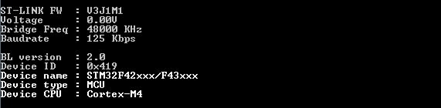
Fig. 109 Connect operation using CAN port 
Note
Not all devices implement this feature. Make sure the device you are using supports a CAN bootloader.
There are other parameters used in connection with the CAN port that have default values, and some others must have specific values. See the tool help for more information.
Example using I2C
STM32_Programmer_CLI -c port=I2C add=0x38 br=400 sm=fast
In the connect command:
The
addparameter changes from one device to another. Refer to AN2606 to determine the correct value. In this case, the STM32F42xxx has a bootloader address equal to0x38.The baudrate parameter
brdepends directly on the speed mode parametersm. For example, ifsm=standard, then the baudrate does not support the value400.
The result of this example is shown in the following figure.

Fig. 110 Connect operation using I2C port 
Note
For each I2C connection operation, the address parameter is mandatory. Not all devices implement this feature. Make sure that the device supports an I2C bootloader.
There are other parameters used in connection with the I2C port that have default values, and some others must have specific values. See the tool help for more information.
Note
For the parallel programming of more than one STM32 device using multiple instances of STM32CubeProgrammer, it is mandatory to add the serial number of each device in the suitable instance, as shown in the following examples:
-c port=swd/usb sn=SN1(instance 1 of STM32CubeProgrammer)-c port=swd/usb sn=SN2(instance 2 of STM32CubeProgrammer)-c port=swd/usb sn=SN3(instance 3 of STM32CubeProgrammer)
I2C direct GPIO command
I2C prerequisites:
Enable I2C on the Linux host.
List buses with:
i2cdetect -lDetect address with:
i2cdetect -y <bus_number>Connect SDA, SCL, and GND.
STM32_Programmer_CLI -c port=i2c-X add=0xYY -d "firmware.bin" "<start_address>"
Example:
STM32_Programmer_CLI -c port=i2c-1 add=0x48 -d "application.bin" 0x08000000
Warnings and notes
Follow AN2606 to enter STM32 bootloader mode.
SPI and I2C pins depend on the selected STM32 device.
Linux users may need permission to access
/dev/spidev*and/dev/i2c-*.
-erase 
Syntax:
[all]: Erase all sectors. EEPROM area is excluded.[<sectorsCodes>]: Erase the sectors identified by codes, for example0,1,2to erase sectors 0, 1, and 2. For EEPROM, useed1anded2.[<[start end]>]: Erase the specified sectors starting from thestartcode to theendcode, for example-e [5 10].
Note
In the case of multiplicity of external loaders, the first selected loader is the one taken into account during erasing of the external memory. In macOS, erasing a range of sectors is not possible with the zsh terminal interpreter. The user must switch to bash to get this command working.
-write 
Syntax:
-w


             <file_path>


             [start_address]
-
[file_path] -
Path of the file to be downloaded.
-
[start_address] -
Start address of download.
Example:
-c port=COM4 -w RefSMI_MDK/All_Flash_0x1234_256K.bin 0x08008000
This command programs the binary file
All_Flash_0x1234_256K.bin
at address
0x08008000. The result is shown in the following figure.
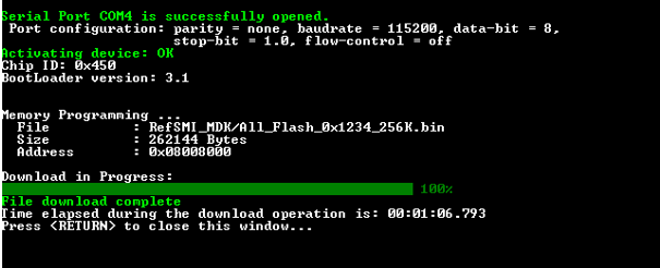
Fig. 111 Download operation 
Note
To verify that the download has been successful, call the verify option
(
-v
or
--verify) just after the write command. Otherwise, the verify
option is ignored.
STM32CubeProgrammer can write on aligned memory regions. Flash memory imposes
a data alignment described in reference manuals. As an example, for STM32U5
devices, the reference manual indicates that this MCU supports
137


              bits
wide data read and write (128 effective bits plus 9 ECC bits), which means
that data must be aligned on 16 bytes.
Mechanisms for programming command
The programming command supports two mechanisms, legacy and incremental, each with its own approach.
In the legacy mechanism, STM32CubeProgrammer reprograms all the flash memory sectors. This process involves erasing and reprogramming the whole memory.
-
[file_path] -
Path of the file to be downloaded.
-
[start_address] -
Start address of download.
The incremental mechanism programs only the modified sectors. This process involves calculating checksums for each sector of the new firmware and the flash memory, comparing them to identify modified sectors, and then selectively erasing and programming only those sectors. This approach significantly reduces the programming time.
Example:
-c port=COM4 -w 1MG.bin 0x08000000 incremental
This command programs the binary file
1MG.bin
at address
0x08000000
using the incremental mechanism. If the new firmware already exists on the flash
memory, no flashing is done.
-verify 
Description
Used for validation of data integrity. It has two mechanisms:
Legacy mechanism: uses a bit-by-bit comparison to verify data integrity.
Fast mechanism: uses a sector-by-sector comparison. If the device does not support checksums, the legacy mechanism is used instead.
–download 
-w32
Description: Downloads the specified 32-bit data into flash memory starting from a specified address.
Syntax:
-w32


             <start_address>


             <32_data_bits>
-
<start_address> -
Start address of download.
-
<32_data_bits> -
32 data bits to be downloaded. Data must be separated by space.
Example:
./STM32_Programmer.sh -c port=/dev/ttyS0 br=9600 -w32 0x08000000 0x12345678 0xAABBCCFF 0x12AB34CD --verify
This command makes it possible to write the 32 data bits
0x12345678,
0xAABBCCFF, and
0x12AB34CD
into the flash memory starting from address
0x08000000.
Note
STM32CubeProgrammer can write on aligned memory regions. Flash memory imposes
data alignment described in reference manuals. As an example, STM32U5 devices
support
137


              bits
wide data read and write (128 effective bits plus 9 ECC
bits), which means that data must be aligned on 16 bytes.
To write into the flash memory, it must already be erased. The
-w32
command does not erase the flash memory.
–read 
Syntax:
--upload


             <start_address>


             <size>


             <file_path>
-
<start_address> -
Start address of read.
-
<size> -
Size of memory content to be read.
-
<file_path> -
Binary file path to upload the memory content.
Example:
./STM32_Programmer.sh -c port=/dev/ttyS0 br=9600 --upload 0x20007000 2000 "/local/benayedh/Binaries/read2000.bin"
This command makes it possible to read 2000 bytes, starting from address
0x20007000, and uploads the content to a binary file
/local/benayedh/Binaries/read2000.bin.
-r32
Description: Read 32-bit data memory.
Syntax:
-r32


             <start_address>


             <size>
Example:
./STM32_Programmer.sh -c port=SWD -r32 0x08000000 0x100
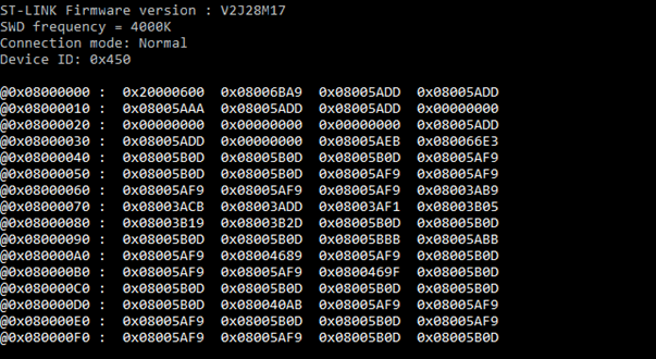
Fig. 112 Read 32-bit operation 
Note
The maximum size allowed with the
-r32
command is 32 Kbytes.
-start 
Syntax:
--start


             [start_address]
-
[start_address] -
Start address of application to be executed.
Example:
./STM32_Programmer.sh --connect port=/dev/ttyS0 br=9600 --start 0x08000000
This command runs the code specified at
0x08000000.
Debug commands
-rst 
-rst
Syntax: -rst
-hardRst 
Syntax: -hardRst
–power 
Description: Controls the target board power through an ST-LINK probe that supports this capability.
The command can be used even without the -c connect command.
Syntax:
-pwr,


             --power


             <on/off>


             [index=<number>]
Parameters
<on/off>: Selects the power state to apply to the target board.index=<number>: Index of the debug probe. Optional when only one probe is connected.
Notes
Available only on ST-LINK probes supporting power control.
If several probes are connected, specify
index=<number>.
Examples
Using
--power
with
-c
STM32_Programmer_CLI.exe -c port=swd --power off index=0 --power on index=0
Using
--power
without
-c
STM32_Programmer_CLI.exe --power off index=0 --power on index=0
-halt 
Syntax: -halt
-step 
Syntax: -step
-score 
Syntax: -score
-coreReg 
Syntax:
-coreReg


             [<core_register>]
Supported core registers:
R0
/
..
/
R15
/
PC
/
LR
/
PSP
/
MSP
/
XPSR
/
APSR
/
IPSR
/
EPSR
/
PRIMASK
/
BASEPRI
/
FAULTMASK
/
CONTROL
-
[core_reg=<value>] -
The value to write in the core register for a write operation. Multiple registers can be handled at once.
Example:
-coreReg
This command displays the current values of the core registers.
-coreReg R0 R8
This command displays the current values of
R0
and
R8.
-coreReg R0=5 R8=10
This command modifies the values of
R0
and
R8.
Note
The following commands are available only with the JTAG/SWD debug port: -rst, -halt, -step, -score, -coreReg.
-list 
Syntax:
-l,


             --list
Example:
./STM32_Programmer.sh --list
The result of this example is shown in the following figure.
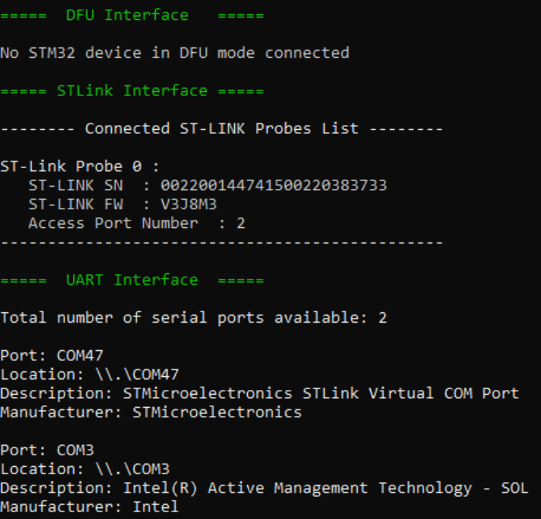
Fig. 113 List of available serial ports 
-getTargetSelList 
SWD Multidrop
SWD (Serial Wire Debug) Multidrop is an enhancement to the standard SWD protocol, commonly used to debug microcontrollers based on Cortex-M cores. This feature allows a single SWD interface, from a debugger or programmer, to communicate with multiple target devices connected on the same SWD bus.
Only flash and option bytes (OB) programming are supported.
Syntax:
-getTargetSelList
The result of this command is shown in the following figure.
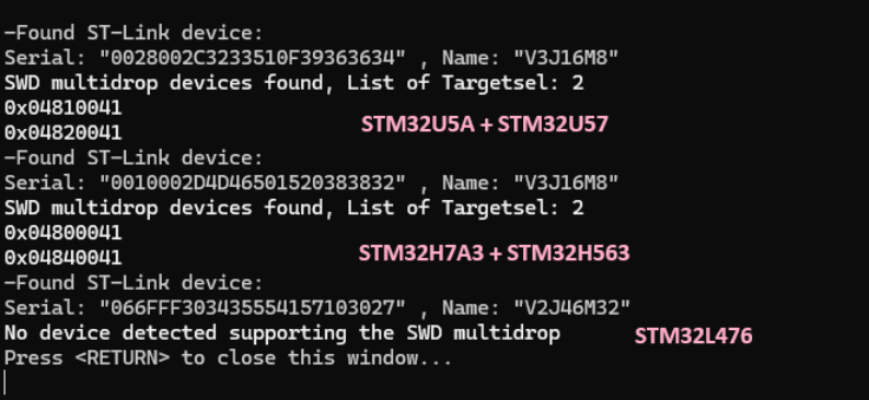
Fig. 114 List of connected devices via different ST-LINK 
Note
If no board is detected, the command returns
No


              STM32


              Target


              Found!
If the connected boards use an outdated ST-LINK firmware, the command returns
Too


              Old


              Firmware,


              please


              upgrade


              your


              STLINK!
Once the ST-LINK firmware is updated, all connected devices supporting the SWD Multidrop are correctly listed.
Limitation: only devices with different
TargetSel
can be connected simultaneously to the same ST-LINK.
New option in Connect command:
TargetSel
Description: Specifies the target device by its
TargetSel
value.
Syntax:
TargetSel=<TargetSelValue>
Example:
./STM32_Programmer_CLI -c port=swd sn="002F00373038510934333935" TargetSel=0x04540041 -d "C:\Users\path.bin" 0x08000000
Note
If multiple boards are connected via the ST-LINK bus, you can perform read, write, and download operations on each board by selecting the appropriate
TargetSel.
Switching between devices can be done without hardware intervention only by selecting the
TargetSel
value.
If multiple ST-LINKs are connected, you must specify the serial number (
sn) in addition to
TargetSel
in the command line.
It is not possible to insert several targets that cannot be selected only by the SWD multi-drop selection sequence. This means that all devices on the lines must have different
TargetSel
values.
For more details, refer to AN6382,
Introduction


              to


              SWD


              multi-drop


              for


              STM32


              with


              ST-LINK
, available on
www.st.com.
-quietMode 
QuietMode command
Syntax:
-q,


             --quietMode
Example:
./STM32_Programmer.sh -c port=/dev/ttyS0 br=115200 --quietMode -w binaryPath.bin 0x08000000
-rstbl 
Bootloader reset command
Syntax:
-rstbl
Example (for SPI):
-c port=spi -rstbl
-vb 
Verbosity command
Description: This command makes it possible to display more messages, to be more verbose.
Syntax:
-vb


             <level>
<level>: Verbosity level, value in
{1,


             2,


             3}
, default value
vb=1.
Example (result shown in the following figure):
./STM32_Programmer.sh -c port=/dev/ttyS0 br=115200 -vb 3
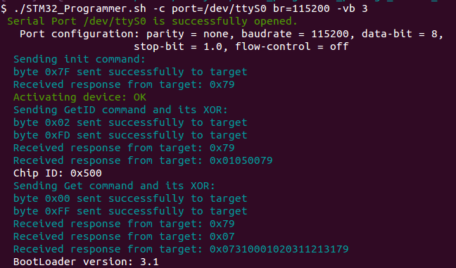
Fig. 115 Verbosity command 
-log 
Log command
Description: This traceability command makes it possible to store the whole traffic (with maximum verbosity level) into a log file.
Syntax:
-log


             [filePath.log]
[filePath.log]: Path of log file, default is
$HOME/.STM32CubeProgrammer/trace.log.
Example:
./STM32_Programmer.sh -c port=/dev/ttyS0 br=115200 -log trace.log
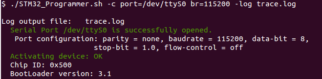
Fig. 116 Log command 
The log file trace.log contains verbose messages:
-el 
External loader command
Description: This command allows entering the path of one or more external memory loaders to perform programming, write, erase, and read operations with an external memory.
Syntax:
-el


             [externalLoaderFilePath1.stldr]
-
[externalLoaderFilePath1.stldr] -
Absolute path of an external loader file.
Syntax:
-el


             [externalLoaderFilePath1.stldr]


             ...


             -el


             [externalLoaderFilePath10.stldr]
-
[externalLoaderFilePath1.stldr] ... [externalLoaderFilePath10.stldr] -
Absolute paths of external loader files.
Example 1:
./STM32_Programmer.sh -c port=swd -w "file.bin" 0x90000000 -v -el "/local/user/externalLoaderPath.stldr"
Example 2:
./STM32_Programmer.sh -c port=swd -e all -el "/local/user/externalLoaderPath.stldr"
Example 3:
./STM32_Programmer.sh -c port=swd -w "file.bin" 0x90000000 -v -el "/local/user/externalLoaderPath1.stldr" "/local/user/externalLoaderPath2.stldr"
Note
This command is supported only with SWD/JTAG ports. A maximum of ten external loaders can be used. It is recommended to use the normal connection mode when trying to download data in an external memory.
-elbl 
External loader bootloader command
Description: With this command, the user can provide the path of an external memory loader used to perform programming, write, erase, and read operations using bootloader interfaces. The command is used for both SFI and external memory programming via bootloader interfaces. When accessing the external memory via bootloader, the open bootloader is loaded into RAM to perform all the operations using bootloader interfaces.
Syntax:
-elbl


             [externalLoaderFilePath.stldr]
-
[externalLoaderFilePath.stldr] -
Absolute path of external loader file.
Example 1:
STM32_Programmer_CLI.exe -c port=usb1 -elbl MX25LM51245G_STM32L552EEVALSFIX-BL.stldr -sfi out.sfix hsm=0 license.bin -rsse RSSe\L5\enc_signed_RSSe_sfi_jtag.bin
Example 2 (external memory programming):
STM32_Programmer_CLI.exe -c port=usb1 -elbl MX66UW1G45G_STM32H7S78-DKSFIx.stldr -w file.bin 0x70000000
Note
This command is supported only with bootloader interfaces to program an external memory in SFIx or OpenBootloader-STM32H7R/S scenarios.
To program an external memory via bootloader, each time the device is disconnected, perform a hardware reset. For STM32H7RS products, choose the external loaders ending with
-SFIx.
External loader for SFIx
The external loader for SFIx operation is aligned with
RSSe_SFI_CallNsFunction. As a result, all the functions used inside the external loader must have the same signature as this function.

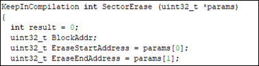
As a consequence the implementation of these function inside the external loader must be slightly modified to be synchronized with input parameters. Example of Sector erase function after modification:
–readunprotect 
Description: This command removes the memory read protection by changing the RDP level from level 1 to level 0.
Syntax:
--readunprotect
Example:
./STM32_Programmer.sh -c port=swd -rdu
–tzenregression 
Description: This command removes TrustZone protection by disabling TZEN from 1 to 0.
Syntax:
--tzenregression
Example:
./STM32_Programmer.sh -c port=usb1 -tzenreg
Note
This command is only supported for bootloader interfaces and MCUs with trusted zone.
-ob 
Option bytes command
Description: This command allows the user to manipulate the device option bytes by displaying or modifying them.
Syntax:
-ob


             [displ]
/
-ob


             [OptByte=<value>]
[displ]: Allows the user to display the whole set of option bytes.
[OptByte=<value>]: Allows the user to program the given option byte.
Example:
./STM32_Programmer.sh -c port=swd -ob rdp=0x0 -ob displ
Note
For more information about device option bytes, refer to the dedicated sections in the programming manual and reference manual, both available on www.st.com.
-safelib 
Description: This command allows a firmware file to be modified by adding a load area (segment) containing the computed CRC values of the user program.
Supported formats: bin, elf, hex and Srec.
Syntax:
-sl


             <file_path>


             <start_address>


             <end_address>


             <slice_size>


             [pattern]
-
<file_path> -
File path (bin, elf, hex or Srec).
-
<start_address> -
Flash memory start address.
-
<end_address> -
Flash memory end address.
-
<slice_size> -
Size of data per CRC value (only
0x400is supported). -
[pattern] -
Optional pattern value from
0x00to0xFF(default is0x00).
Example
STM32_Programmer_CLI.exe -sl TestCRC.axf 0x8000000 0x8010000 0x400

Fig. 117 Safety lib command 
The flash program memory is divided into slices, whose size is given as a parameter to the safety lib command as shown in the example above. For each slice a CRC value is computed and placed in the CRC area. The CRC area is placed at the end of the memory, as shown in
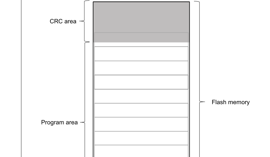
Fig. 118 Flash memory mapping 
The address and size of the CRCs area are determined as follows:
CRCs_Area_Size = Flash_Size / Slice_Size * 4 bytes
CRCs_Start_Address = Flash_End_Address - CRCs_Area_Size
The CRC values in the CRC area are placed according to the position(s) of the user program in the flash memory
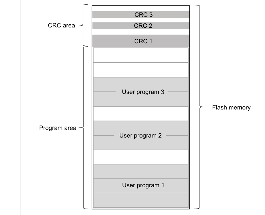
Fig. 119 Flash memory mapping example 
The tool checks the syntax and the processing of the command, and marks a failure if there is a parameters mismatch or a problem in the CRC calculation by displaying various error message:
“Invalid file path or wrong file extension”
<file_path>has an unrecognized extension:.bin.binary.hex.srec.s19.elf.axf.out.“The safety lib command is missing parameters” The passed command does not respect the parameters number.
“Invalid flash start address”
<start_address>is not correct (exceeds0xFFFFFFFFas max value) or is not in hexadecimal format.“Invalid flash end address”
<end_address>is not correct (exceeds0xFFFFFFFFas max value) or is not in hexadecimal format.“Invalid slice size”
<slice_size>is not correct (exceeds0xFFFFFas max value) or is not in hexadecimal format.“Invalid pattern”
<pattern>is not in the range[0x00 to 0xFF]or is not in hexadecimal format.“The slice size is larger than the flash size”
<slice_size>is larger than the dedicated flash size (<end_address> - <start_address>).“The slice size is invalid” The dedicated flash memory is not aligned (based on
<slice_size>).“File is Read Only” The input file
<file_path>is not editable.“No segments in this file” The input
<file_path>does not contain any data segment.“The segment {x} of {y} does not start at the beginning of a flash slice” The current treated segment does not start at the beginning of the flash slice.
Secure programming SFI specific commands
Secure firmware install (SFI) is a feature supporting secure firmware flashing, available on some STM32 devices. The firmware provider has the possibility to protect its internal firmware against any illegal access, and to control the number of devices that can be programmed.
The protected firmware installation can be performed using different communication channels, such as JTAG/SWD or bootloader interfaces (UART, SPI and USB). For more details refer to AN5054.
-sfi 
SFI command
Description: Programs an sfi file.
Syntax: -sfi [<protocol=Ptype>] <.sfi file_path> [hsm=0|1] <lic_path|slot=slotID> [<licMod_path>|slot=slotID]
[<protocol=Ptype>] Protocol type to be used: static/live (only static protocol is supported so far), default: static.
<file_path> Path of sfi file to be programmed.
[hsm=0|1] Sets user option for HSM use value {0 (do not use HSM), 1 (use HSM)}, default: hsm = 0.
<lic_path|slot=slotID> Path to the SFI license file (if hsm = 0) or reader slot ID if HSM is used (hsm = 1).
-rsse 
RSSe command
Description: This command allows the user to select the root secure services extension library (RSSe). Mandatory for devices using RSSe to make secure firmware install (SFI). The RSSe binary file can be found in STM32CubeProgrammer bin/RSSe folder.
Syntax: -rsse <file_path>
<file_path> Path of RSSe file
-a 
Abort command
Description: This command allows the user to clean a not properly finished process. The currently ongoing operation stops and the system returns to idle state.
Syntax: -a
-mcsv 
MCSV command
Description: This command allows the user to select the modules file including the list of modules to be installed with SFI. This option is mandatory when the SFI image integrates at least one module (area of type m).
Syntax: -mcsv <module_path.mcsv>
<module_path.mcsv> : Path of mcsv fil
Secure programming SFIx specific commands Secure firmware install (SFIx) is a feature supporting secure external firmware flashing, available on some STM32 devices with OTFDEC capability. The firmware provider has the possibility to protect its external firmware/data against any illegal access, and to control the number of devices that can be programmed. The SFIx secure programming can be carried out only with JTAG/SWD interface. For more details refer to AN5054
-sfi 
SFIx command
Description: Programs an sfix file.
Syntax: -sfi [<protocol=Ptype>] <.sfix file_path> [hsm=0|1] <lic_path|slot=slotID> [<licMod_path>|slot=slotID]
[<protocol=Ptype>] Protocol type to be used: static/live (only static protocol is supported so far), default: static. <file_path> Path of sfi file to be programmed. [hsm=0|1] Sets user option for HSM use value {0 (do not use HSM), 1 (use HSM)}, default: hsm = 0. <lic_path|slot=slotID> Path to the SFI license file (if hsm = 0) or reader slot ID if HSM is used (hsm = 1). -el –extload Selects a custom external memory-loader, only for the JTAG/SWD interfaces <file_path> External memory-loader file path -elbl –extloadblSelects a custom external memory-loader for the bootloader interface <file_path> External memory-loader file path
-rsse 
RSSe x command
Description: This command allows the user to select the root secure services extension library (RSSe). Mandatory for devices using RSSe to make secure firmware install (SFI). The RSSe binary file can be found in STM32CubeProgrammer bin/RSSe folder.
Syntax: -rsse <file_path>
<file_path> Path of RSSe file
-a 
Abort SFI command
Description: This command allows the user to clean a not properly finished process. The ongoing operation stops and the system returns to idle state.
Syntax: -a
Note: The ExternalLoader is different for SFIx use case, as some initializations are already done by RSS, and it is marked with –SFIX at the end of the External FlashLoader name.
-mcsv 
MCSV SFI command
Description: This command allows the user to select the modules file including the list of modules to be installed with SFI. This option is mandatory when the SFI image integrates at least one module (area of type m).
Syntax: -mcsv <module_path.mcsv>
<module_path.mcsv> : Path of mcsv file
-ecsv 
Description: This command is used for Secure Manager Secure Modules install in external flash. It allows the user to select the modules file including the list of external modules to be installed with SFIx. This option is mandatory when the SFI image integrates at least one external module (area of type e).
Syntax: -ecsv : Path of ecsv file
<exmodule_path.ecsv>: Path of ecsv file
HSM related commands
To control the number of devices that can be programmed, ST offers a secure firmware flashing service based on HSM (hardware secure module) as a license generation tool to be deployed in the programming house.
Two HSM versions are available:
HSMv1: static HSM, it allows the user to generate firmware licenses for STM32 secure programming of devices selected in advance.
HSMv2: dynamic HSM, it is an updated version of the previous one, allows the generation of firmware licenses targeting STM32 secure programming of devices chosen via personalization data at the OEM site.
Before using the HSM, it must be programmed using Trusted Package Creator. This tool can program both versions with some specific input configurations, as detailed in UM2238. For more details, refer to AN5054.
-hsmgetinfo 
Description: Reads the HSM available information.
Syntax: -hsmgetinfo [slot=<SlotID>]
[slot=<SlotID>] Slot ID of the smart card reader Default value: slot = 1 (the PC integrated SC reader)
-hsmgetcounter 
Description: Reads the current value of the license counter.
Syntax: -hsmgetcounter [slot=<SlotID>]
[slot=<SlotID>] Slot ID of the smart card reader Default value: slot = 1 (the PC integrated SC reader)
-hsmgetfwid 
Description: Reads the Firmware/Module identifier.
Syntax: -hsmgetfwid [slot=<SlotID>]
[slot=<SlotID>] Slot ID of the smart card reader Default value: slot = 1 (the PC integrated SC reader)
-hsmgetstatus 
Description: Reads the current card life-cycle state.
Syntax: -hsmgetstatus [slot=<SlotID>]
[slot=<SlotID>] Slot ID of the smart card reader Default value: slott = 1 (the PC integrated SC reader)
-hsmgetlicense 
Description: Gets a license for the current chip if counter is not null.
Syntax: -hsmgetlicense <file_path> [slot=<SlotID>] [protocol=<Ptype>]
<file_path> File path into where the received license is stored [slot=<SlotID>] Slot ID of the smart card reader Default value: slot = 1 (the PC integrated SC reader) [<protocol=Ptype>] Protocol type to be used: static/live Only static protocol is supported so far Default value: static
–hsmglfcb 
Description: Gets a license for the current certificate binary file if counter is not null.
Syntax: -hsmglfcb <certif_file_path.bin> <license_file_path.bin> [slot=<SlotID>] [protocol=<Ptype>]
<certif_file_path.bin> File path from which the input certificate is read. <license_file_path.bin> File path where the received license is stored [slot=<SlotID>] Slot ID of the smart card reader. Default value: slot = 1 (the PC integrated SC reader)
STM32WB specific commands 
-antirollback 
Description: Perform the antirollback operation.
Syntax: -antirollback
-startfus 
Description: Start the FUS.
Syntax: -startfus
-getuid64 
Description: Read the device unique identifier (UID).
Syntax: -getuid64
-fusgetstate 
Description: Read the FUS state.
Syntax: -fusgetstate
Note: FUS operator version is not available via bootloader interfaces.
-fwdelete 
Description: Delete the BLE stack firmware.
Syntax: -fwdelete
-fwupgrade 
Description: Upgrade of BLE stack firmware or FUS firmware.
Syntax: -fwupgrade <file_path> <address> [firstinstall=0|1] [startstack=0|1] [-v]
<file_path> New firmware image file path <address> Start address of download [firstinstall=0|1] 1 for the first installation, otherwise 0 Optional, default value firstinstall=0 [startstack=0|1] 1 to start the stack after the upgrade, otherwise 0 Optional, default value startstack=1 [-v] Verify if the download operation is completed successfully before starting the upgrade
-startwirelessstack 
Description: Start the wireless stack.
Syntax: -startwirelessstack
-authkeyupdate 
Description: Authentication key update.
Syntax: -authkeyupdate <file_path>
-authkeylock 
Description: Authentication key lock. Once locked, it is no longer possible to change it using -authkeyupdate command.
Syntax: -authkeylock
-wusrkey 
Description: Write user key.
Syntax: -wusrkey <file_path> <keytype=1|2|3>
-swv 
Description: This command allows the user to access the serial wire viewer console mode, which displays the printf data sent from the target through SWO.
Syntax: -swv <freq=<frequency>> <portnumber=0-31|all> [<file_path.log>] [-RA]
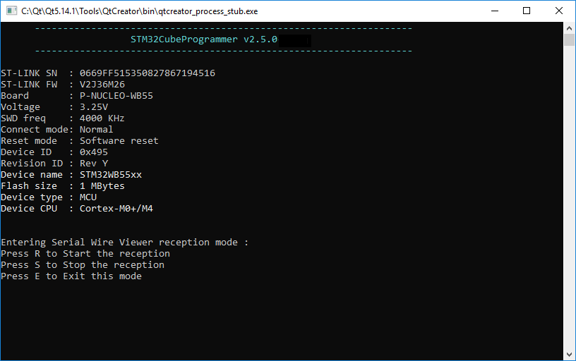
Fig. 120 SWV command 
-startswv 
Description: This command allows the user to access the serial wire viewer console mode.
Syntax: -startswv <freq=<frequency>> <portnumber=0-31|all> [<file_path.log>]
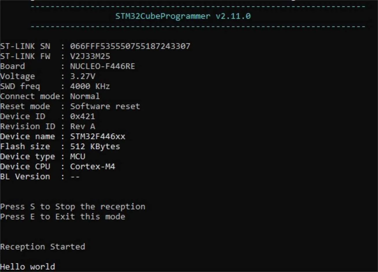
Fig. 121 startswv command 
-dsecurity 
Description: This command allows the user to disable security on STM32WL.
Syntax: -dsecurity
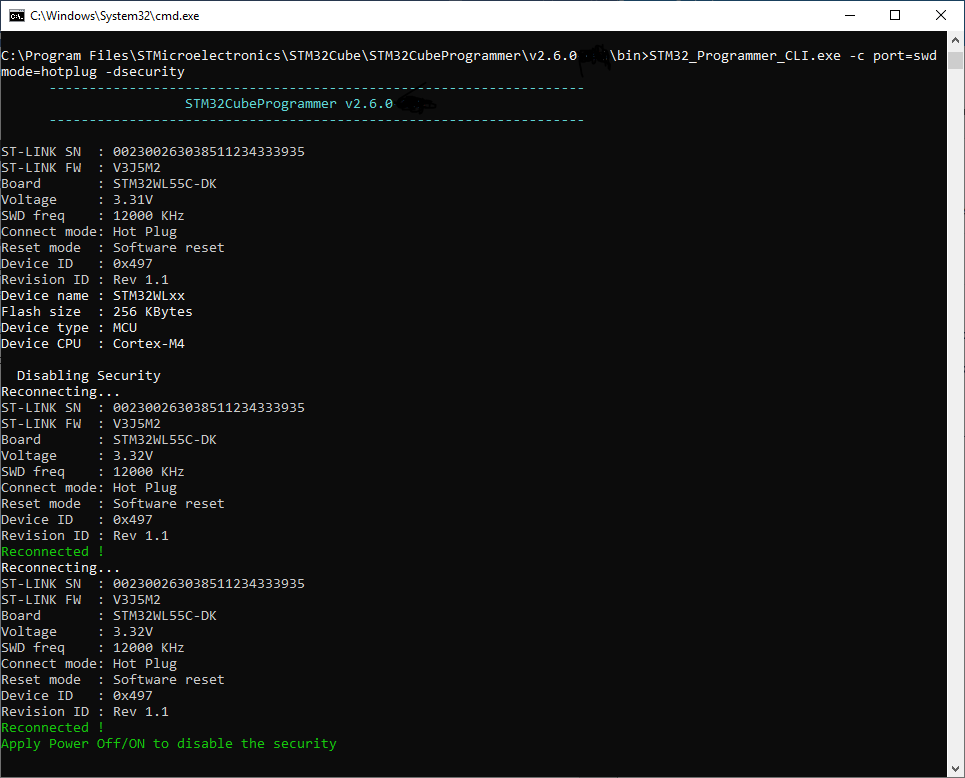
Fig. 122 Disable security 
-setdefaultob 
Description: This command allows the user to configure option bytes to their default values on STM32WL.
Syntax: -setdefaultob
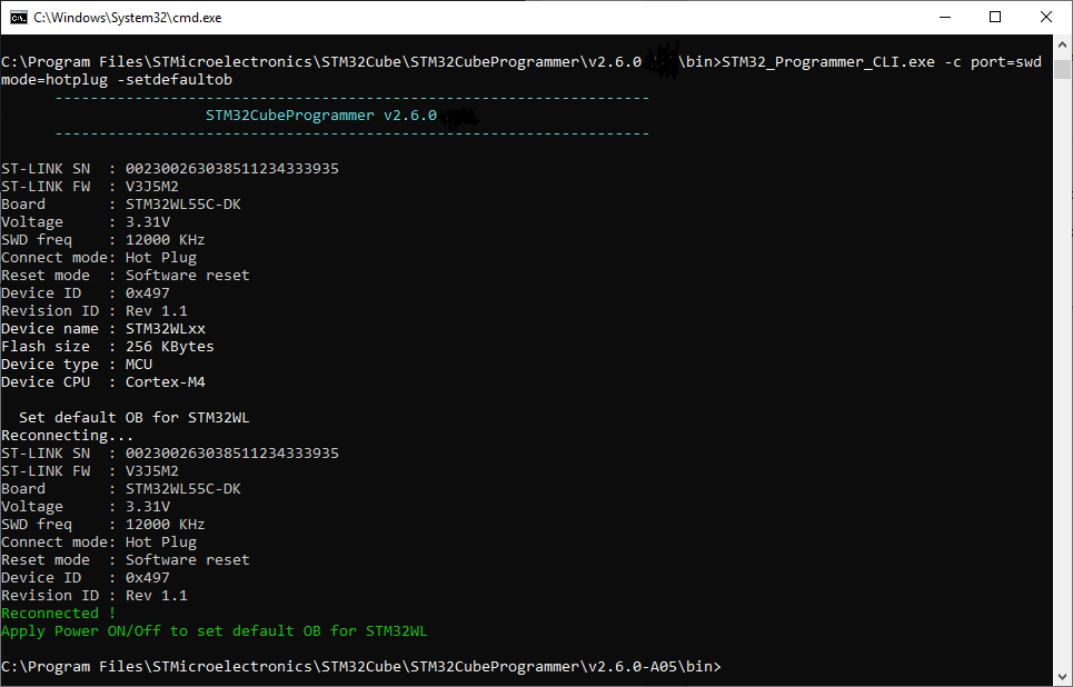
Fig. 123 Configure option bytes to their default values 
-unlockchip 
Description: This command allows the user to unlock the device if bad option bytes are programmed.
Syntax: -ob unlockchip
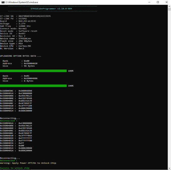
Fig. 124 Output of unlockchip command 
Note: If SFI command finishes with a fail, the STM32WL chip must be set in its default status using the disable security command line (-dsecurity), then the set default option byte command line (-setdefaultob).
-ssigfoxc 
Description: This command allows the user to save the chip certificate to a binary file.
Syntax: -ssigfoxc <binary_file_path>
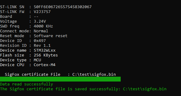
Fig. 125 Example of -ssigfoxc command 
-wsigfoxc 
Description: This command allows the user to write the chip certificate at address 0x0803E500.
Syntax: -wsigfoxc <binary_file_path> <address>
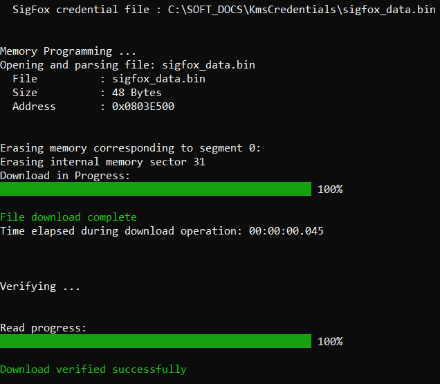
Fig. 126 Example 1 of -wsigfoxc command 
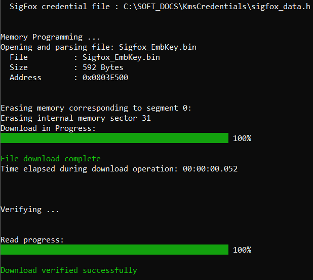
Fig. 127 Example 2 of -wsigfoxc command 
-regdump 
Description: Reads and dumps core and MCU registers.
Syntax: -regdump <file_path.log> [choice=<number>]
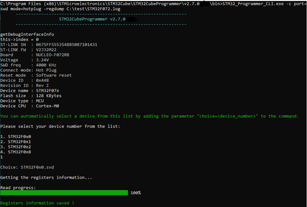
Fig. 128 Read core and MCU registers 
-hf 
Description: Starts hard fault analysis and displays the output trace needed to understand the fault reason.
Syntax: -hf
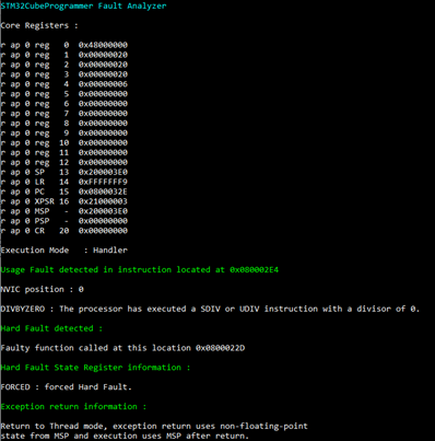
Fig. 129 Fault analyzer CLI view when Hard Fault is detected 
-fchecksum 
Description: Calculates the checksum value for the entire file content using an addition algorithm and displays the resulting value.
Syntax: -fchecksum, –file-checksum <file_path>
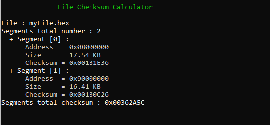
Fig. 130 Example of File checksum command 
-checksum 
Description: Calculates the checksum value for any accessible memory type, including internal flash memory, and displays the resulting output.
Syntax: -checksum, –checksum <address> <size>
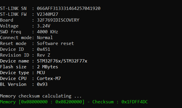
Fig. 131 Checksum command output for the internal flash memory 
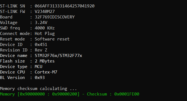
Fig. 132 Checksum command output for an external memory 
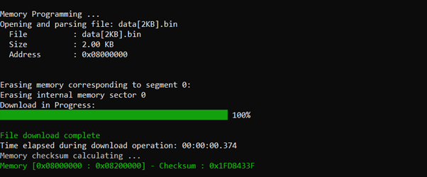
Fig. 133 Checksum command output at the end of file download 
-lockRDP1 
Description: Allows the user to lock the RDP regression from level 1 with a password.
Syntax: -lockRDP1 <OEM1 least significant bytes key> <OEM1 most significant bytes key>
-lockRDP2 
Description: Allows the user to lock the RDP regression from level 2 with a password.
Syntax: -lockRDP2 <OEM2 least significant bytes key> <OEM2 most significant bytes key>
-unlockRDP1 
Description: Allows the user to unlock the RDP regression from level 1 with a password.
Syntax: -unlockRDP1 <OEM1 least significant bytes key> <OEM1 most significant bytes key>
-unlockRDP2 
Description: Allows the user to unlock the RDP regression from level 2 with a password.
Syntax: -unlockRDP2 <OEM2 least significant bytes key> <OEM2 most significant bytes key>
-lockbs 
Description: This command provisions the BS Key, which is a 32-bit password allowing RDP transition from L2 with boundary scan to L2.
Syntax: -lockbs <BSKEY>
-unlockbs 
Description: This command performs the RDP transition using the provisioned BSKEY or 0xAAAAAAAA if no BSKEY provisioning has been done.
Syntax: -unlockbs <BSKEY>
-gc 
Description: This command allows the user to read the chip certificate.
Syntax: -gc certification.bin
-w32dbgmcu 
Description: Downloads the specified 32-bit data into the DBGMCU AUTH HOST register to place a message in the mailbox shared between the device and the host.
Syntax: -w32dbgmcu <32_data_bits>
-sdp 
Description: This is a security feature to program OBKey content.
Syntax: -sdp [OBKey_File_Path.obk]

Fig. 134 OBKey provisioning example 
-pwd 
Description: This command provisions the password in OTP and generates a password.bin file to be used later for regression or debug authentication.
Syntax: -pwd value=<password> path=<PasswordOPath>
-debugauth 
Description: Performs discovery, authentication using password or certificate files, or debug close operations for supported devices.
Syntax: debugauth=2 / pwd=[password_path.bin] debugauth=1 / per=[Permission] key=[Key_Path.pem] cert=[Certificate_Path.b64] debugauth=1 / debugauth=3
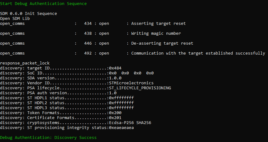
Fig. 135 Discovery log 
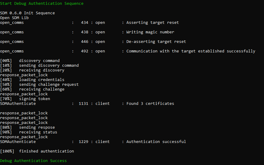
Fig. 136 Debug authentication with password 
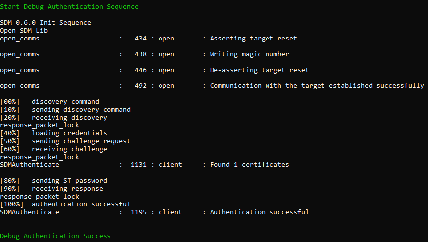
Fig. 137 Debug authentication with certificate 
–force_no_da 
Description: This option forces the product state to OB programming even when debug authentication is not configured.
Syntax: –force_no_da
-installipmodule 
Description: Installs a Secure Manager module using HSM or a global license.
Syntax: -installipmodule <file_path> [hsm=0|1] [slot=slotID] [address]
-updateipmodule 
Description: Updates a Secure Manager module.
Syntax: -updateipmodule <file_path> <address>
-skiperase 
Description: Skips sector erase before programming.
Syntax: –skiperase
-storekeyotp 
Description: Stores the authentication public key in the OTP. This command applies only to STM32WB0x and STM32WL33 devices and can be performed only with UART.
Syntax: -storekeyotp <key_path> <start_address>
-rssekw 
Description: Allows the user to select the RSSeKW library for key wrapping and execute wrapping of the private key provisioned or provided by the user.
Syntax: -rssekw <rssekw .bin file path> <wrapping output file path> [KeyType=eccchipfu|eccchiplu] [ExportPublicKey=yes|no] [WrappingKeySelect=dhuk] [KeyUsage=ecc_usage_sign|ecc_usage_scalar_mul] [SecAttr=secure|non_secure] [PrivAttr=privilege]
<.bin file_path>: RSSe key wrapping file path.<.bin file_path>: Output.binfile path.[KeyType=<eccchipfu|eccchiplu>]: Private key to wrap.[ExportPublicKey=<Yes|No>]: Generate or not the public key.[WrappingKeySelect=<DHUK>]: Method used to wrap the private key.KeyUsage=<ECDSA_USAGE_SIGN|ECC_USAGE_SCALAR_MUL>[]: Usage of the private key.[SecAttr=<SECURE|NON_SECURE>]: Secure or nonsecure context.[PrivAttr=<PRIVILEGE|NON_PRIVILEGE>]: Privileged or unprivileged context. Value =Privilegefor ECC chip.
For STM32H5 series:
Syntax: -rssekw <rssekw.bin file path> <wrapping output file path> [KeyType=eccchipfu|eccchiplu] [ExportPublicKey=yes|no] [WrappingKeySelect=dhuk] [KeyUsage=ecc_usage_sign|ecc_usage_scalar_mul] [SecAttr=secure|non_secure] [PrivAttr=privilege] [epochsel=0xFFF277D1]
[epochsel=0xFFF277D1] Epoch select value, for ECC chip private keys. Only one value is possible: 0xFFF277D1.
-r32fast 
Description: Fast read 32-bit data memory.
Syntax: -r32fast
–yes 
Description: STM32V8 PCM programming «Power pulse » mode presents extra programming constraint, only four trials are allowed for internal memory programming (including OTP programming). When setting the Option Byte PM=1, the internal memory can be programmed only five times, four times for OTP programming, beyond this limit there is a risk of loosing the V8 devices. The tool automatically blocks this operation and raises an error. The user should re-enter the command adding: -y/–yes.
Syntax: -y, –yes
Example:
./STM32_Programmer_CLI -c port=swd -d "C:\Users\path.bin" 0x08000000 -y
-blankcheck 
Description: This command allows the user to verify that the STM32 flash memory is blank. If this is not the case, the first address with data is highlighted in a message.
Syntax:
-blankcheck
Example:
STM32_Programmer_CLI.exe -c port=swd -blankcheck
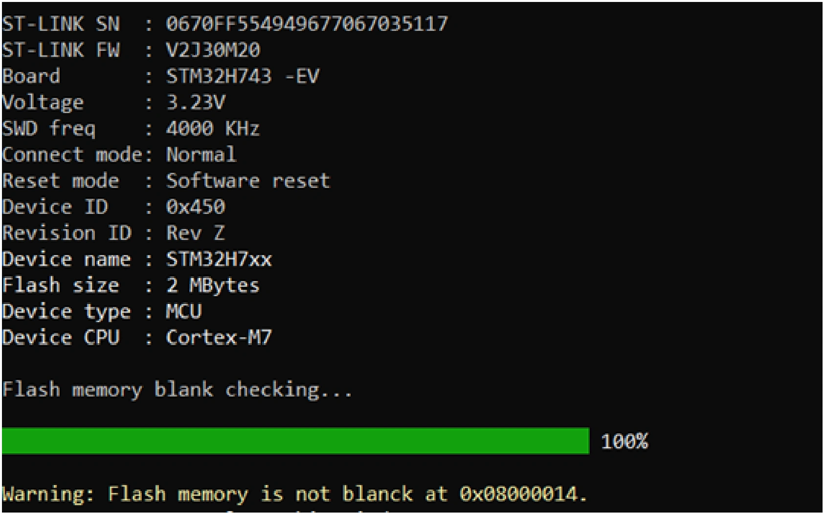
Fig. 138 Example 1: memory is not blank at address 0x08000014 
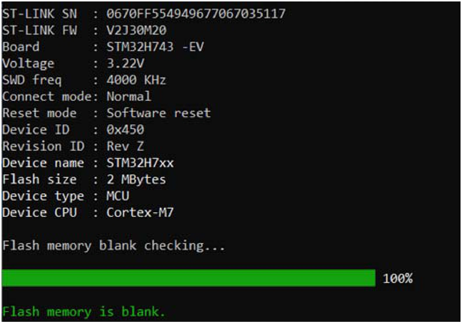
Fig. 139 Example 2: memory is blank 
-fillmemory 
Syntax:
-fillmemory <start_address> [size=<value>] [pattern=<value>] [datawidth=8|16|32]
Examples:
Example 1:
STM32_Programmer_CLI.exe -c port=swd -fillmemory 0x08000000 size=0x10 pattern=0XAA datawidth=16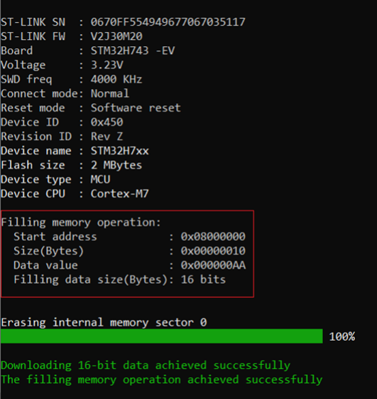
Fig. 140 Fill memory command - Example 1
Example 2:
STM32_Programmer_CLI.exe -c port=swd -fillmemory 0x08000000 size=0x10 pattern=0XCC datawidth=32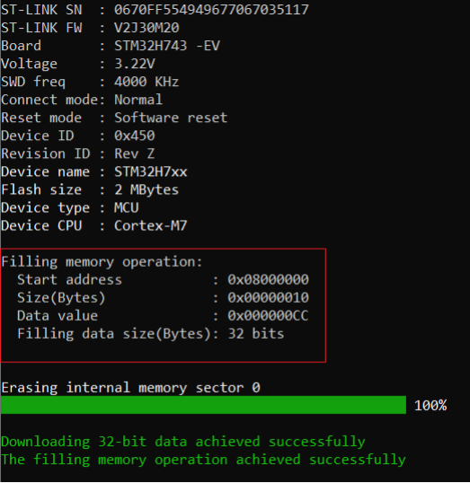
Fig. 141 Fill memory command - Example 2
<start_address>:
Start address for write. The address
0x08000000
is used by default.
[size=<value>]:
Size of the data to write.
[pattern=<value>]:
The pattern value to write.
[datawidth=8|16|32]:
Filling data size can be 8, 16, or 32 bits. The selected value by default is 8 bits.