
 STM32CubeProgrammer

Main window 
The main window is composed of the parts described in the following sections.
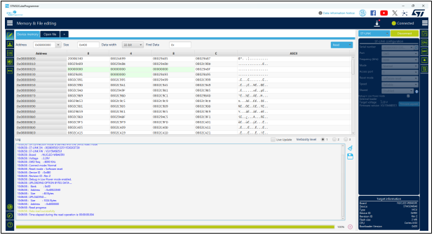
Fig. 13 STM32CubeProgrammer main window 
Main menu 
This menu allows the user to switch between the three main panels of the Memory and file editing, Erasing & programming, and Option bytes tools. The other panels are displayed according to the used device. By clicking on the Hamburger menu (the three-line button) on the top left corner, the menu expands and displays the textual description shown.
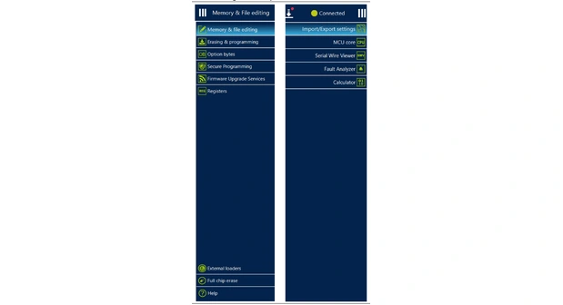
Fig. 14 Expanded main menu 
Log panel 
Displays errors, warnings, and informational events related to the operations executed by the tool. The verbosity of the displayed messages can be refined using the verbosity ratio buttons above the log text zone. The minimum verbosity level is 1, and the maximum is 3 (all transactions via the selected interface are logged). All displayed messages are time stamped with the format “hh:mm:ss:ms”, where “hh” is for hours, “mm” for minutes, “ss” for seconds and “ms” for milliseconds (in three digits).
On the right of the log panel there are two buttons, the first to clean the log, the second to save it to a log file.
If the selected language of the tool is not English, two log files are saved in the same location, one in English, the other in the selected language.
Progress bar 
The progress bar visualizes the progress of any operation or transaction done by the tool (for example, Read, Write, Erase). Ongoing operations can be aborted by pressing the “Stop” button in front of the progress bar.
Target configuration panel 
This is the first panel to look at before connecting to a target. It allows the user to select the target interface (either the debug interface using ST-LINK/J-Link debug probe, or the bootloader interface over UART, USB, SPI, CAN, or I2C).
With the refresh button the user can check the available interfaces connected to the PC. If this button is pressed while the ST-LINK/J-Link interface is selected, the tool checks the connected ST-LINK/J-Link probes, and lists them in the Serial numbers combo box. If the UART interface is selected, it checks the available communication ports of the PC, and lists them in the Port combo box. If the USB interface is selected, it checks the USB devices in DFU mode connected to the PC, and lists them in the Port combo box. Each interface has its own settings, to set before connection.
ST-LINK settings 
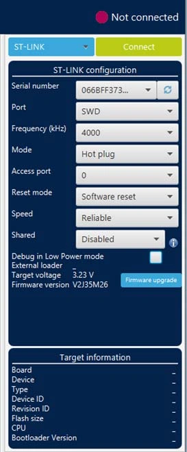
Fig. 15 ST-LINK configuration panel 
- Serial number: this field contains the serial numbers of all connected ST-LINK probes.
The user can choose one of them, based on its serial number.
Port: ST-LINK probe supports two debug protocols, JTAG and SWD.
Note: JTAG is not available on all embedded ST-LINK in the STM32 Nucleo or Discovery boards.
Frequency: the JTAG or SWD clock frequency
Access port: selects the access port to connect to. Most of the STM32 devices have only one access port, which is Access port 0.
- Mode:
Normal: with “Normal” connection mode, the target is reset then halted. The type of reset is selected using the “Reset Mode” option.
Connect under reset: this mode enables connection to the target using a reset vector catch before executing any instructions. This is useful in many cases, for example when the target contains a code that disables the JTAG/SWD pins.
Hot plug: enables connection to the target without a halt or reset. This is useful for updating the RAM addresses or the IP registers while the application is running.
Power down: used to put the target in debug mode, even if the application has not started since the target power-up. The hardware reset signal must be connected between ST-LINK and the target. This feature can be not fully effective on some boards (MB1360, MB1319, MB1361, MB1355) with STMPS2141 power switch.
hwRstPulse: the tool generates a reset pulse, and then connects to the target. This connection mode does not prevent application launch before connection. It is used in some devices where under mode is not available (such as STM32WB0x and STM32WL33)
- Reset mode:
Software system reset: resets all STM32 components except the Debug via the Cortex-M application interrupt and reset control register (AIRCR).
Hardware reset: resets the STM32 device via the nRST pin. The RESET pin of the JTAG connector (pin 15) must be connected to the device reset pin.
Core reset: resets only the Cortex-M via the AIRCR(a).
- Speed (Cortex-M33 only):
Reliable: allows the user to connect with a slow mode.
Fast: allows the user to connect with a fast mode.
Shared: enables shared mode allowing connection of two or more instances of STM32CubeProgrammer or other debugger to the same ST-LINK probe.
Debug in low-power mode (STM32U5/WB/L4 series only): sets the bits in DBGMCU_CR to 1.
External loader: displays the name of the external memory loader selected in the “External loaders” panel accessible from the main menu (Hamburger menu).
Target voltage: target voltage is measured and displayed.
Firmware version: displays the ST-LINK firmware version. The firmware upgrade button allows you to upgrade the ST-LINK firmware.
J-Link settings 
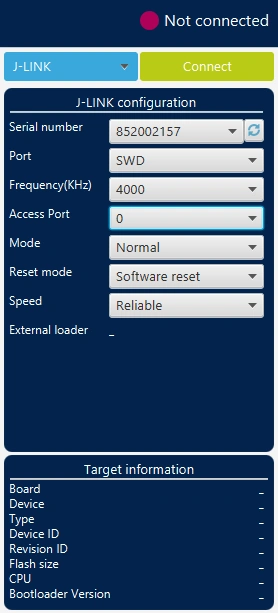
Fig. 16 J-Link configuration panel 
- Serial number: this field contains the serial numbers of all connected J-Link probes.
The user can choose one of them, based on its serial number.
Port: J-Link probe supports only SWD debug protocol.
Frequency: SWD clock frequency (only 4000 kHz is available).
Access port: selects the access port to connect to. Most of the STM32 devices have only one access port (Access port 0).
- Mode:
Normal: the target is reset, then halted. Selected using the “Reset Mode” option.
Connect under reset: enables connection to the target using a reset vector catch before executing any instructions. Useful in many cases, for example when the target contains a code that disables the SWD pins.
Hot plug: enables connection to the target without a halt or reset. Useful to update the RAM addresses or the IP registers while the application is running.
- Reset mode:
Software system reset: resets all STM32 components except the Debug via Cortex-M application interrupt and reset control register (AIRCR).
Hardware reset: resets the STM32 device via the nRST pin. The RESET pin of the SWD connector (pin 15) must be connected to the device reset pin.
Core reset: resets only the Cortex-M via the reset control register(a).
- Speed (Cortex-M33 only):
Reliable: allows the user to connect with a slow mode.
Fast: allows the user to connect with a fast mode.
External loader: displays the name of the external memory loader selected in the External loaders panel accessible from the main menu (Hamburger menu).
UART settings 
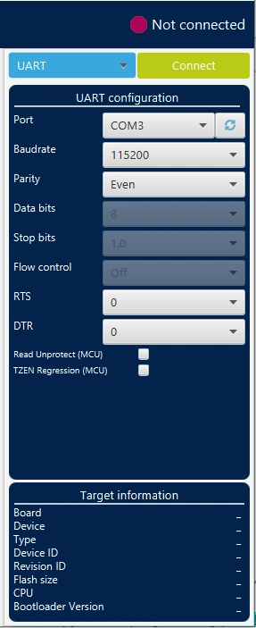
Fig. 17 UART configuration panel 
Note
Core reset does not exist for Cortex-M33, Cortex-M55 and Cortex-M85. The STM32 must boot in bootloader mode using boot pins and/or the option bits. Check AN2606 “STM32 microcontroller system memory boot mode”, available on www.st.com, for more information on the STM32 bootloader.
Port: selects the com port to which the target STM32 is connected. Use the refresh button to recheck the available com port on the PC.
Baudrate: selects the UART baud rate.
Parity: selects the parity (even, odd, none), must be “even” for all STM32 devices.
Data bits: must be always 8, only 8-bit data is supported by the STM32.
Stop bits: must be always 1, only 1-bit stop is supported by the STM32.
Flow control: must be always off.
RTS (request to send): sets the COM RTS pin to either high or low level.
DTR (data terminal ready): sets the COM DTR pin to either high or low level.
USB settings 
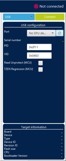
Fig. 18 USB configuration panel 
Port: selects the USB devices in DFU mode connected to the PC. You can use the refresh button to recheck the available devices.
Note:
The STM32 must boot in bootloader mode using boot pins and/or the option bits. Check AN2606, available on www.st.com, for more information.
Note:
Once the correct interface settings are set, click on the “Connect” button to connect to the target interface. If the connection succeeds, it is shown in the indicator above the button, which turns to green.
Once connected, the target information is displayed in the device information section below the settings section, which is then disabled, as shown in the figure below.
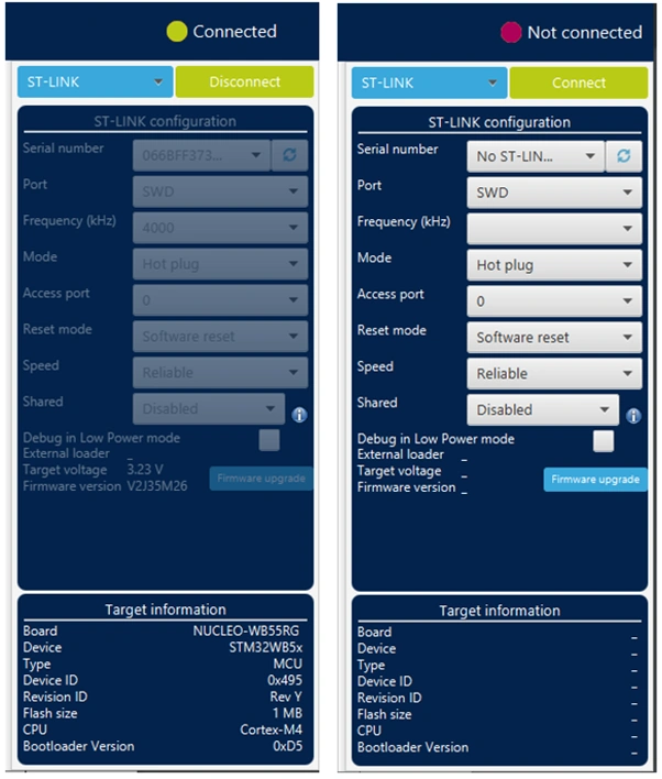
Fig. 19 Target information panel 
SPI settings 
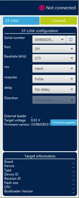
Fig. 20 SPI configuration panel 
Serial number: this field contains the serial numbers of all connected ST-LINK-V3 probes in case of use of SPI bootloader.
Port: selects the SPI devices connected to the PC. Use the refresh button to recheck the available devices.
Baudrate: selects the SPI baud rate.
nss: slave select software or hardware.
nsspulse: the slave selection signal can operate in a pulse mode, where the master generates pulses on nss output signal between data frames for a duration of one SPI clock period when there is a continuous transfer period.
Delay: used to insert a delay of several microseconds between data.
Direction: must be always Full-duplex, both data lines are used, and synchronous data flows in both directions.
I2C settings 
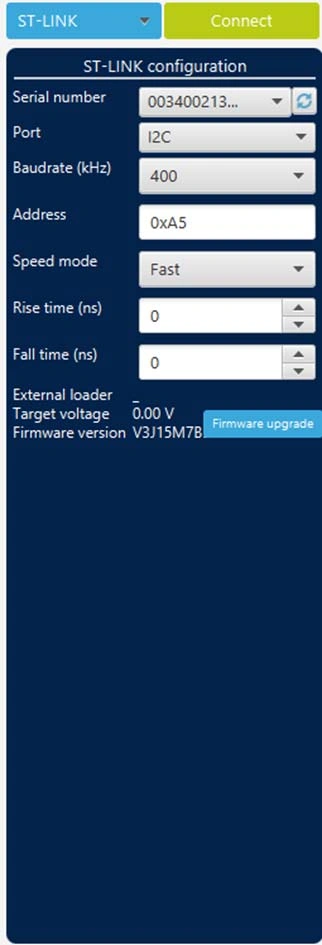
Fig. 21 I2C configuration panel 
Serial number: this field contains the serial numbers of all connected ST-LINK-V3 probes when using the I2C bootloader.
Port: selects the I2C devices connected to the PC. You can use the refresh button to recheck the available devices.
Baudrate: selects the I2C baud rate.
Address: adds the address of the slave bootloader in hex format.
Speed mode: selects the speed mode of the transmission Standard or Fast.
Rise time: chooses values according to Speed mode, 0-1000 (STANDARD), 0-300 (FAST).
Fall time: chooses values according to Speed mode, 0-300 (STANDARD), 0-400 (FAST).