
 STM32CubeProgrammer

Automatic mode 
This feature, shown in Erasing & Programming window (see the figure below), allows the user to program and configure STM32 devices in loop. Allowed actions:
Full chip erase: erases the whole flash memory.
Download file: activates and sets programming options from Download section:
File path.
Start address.
Skip erase before programming.
Verify programming.
Run after programming.
- Option bytes commands: configures the device by setting option bytes command
line.
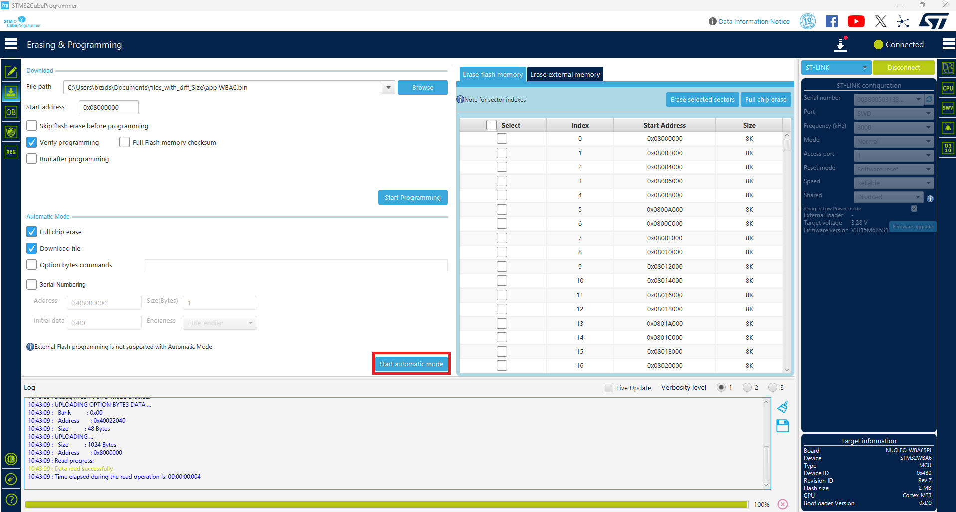
Fig. 29 Automatic mode in Erasing & Programming window 
All automatic mode traces are indicated in the Log panel, to show the process evolution and user intervention messages.
Graphical guide 
- Connection to a first target must be established before performing automatic
mode to collect connection parameters values associated to all next devices.
- If the Download file is checked, the system takes all Download file options
in consideration, otherwise no Download option is performed.
- If the Option bytes commands is checked, the text field is activated, then
the user can insert option bytes CLI commands, and make sure that there are no white spaces at the beginning:
-ob [OptionByte=value] [OptionByte=value] [OptionByte=value] ...
Example of Option bytes command:
-ob BOR_LEV=0 nBOOT0=1.- If the Start automatic mode button is pressed, the system enters in a loop,
until a system stop is called.
- While the automatic mode is in execution state, all graphical objects are
disabled.
- The user can stop the process at any time by pressing Cancel or Stop
automatic mode buttons.
Log messages 
Starting Automatic Mode...Indicates that the system successfully entered the automatic process.
More than one ST-LINK probe detected! Keep only one ST-LINK probe!The automatic mode cannot be used if more than one ST-LINK probe is connected to the computer when using JTAG/SWD interfaces. A message is displayed, asking the user to keep only one ST-LINK probe connected to continue using this mode.
More than one ST-LINK Bridge detected! Keep only one ST-LINK Bridge!The automatic mode cannot be used if more than one ST-LINK bridge is connected to the computer when using bootloader interface SPI/CAN/I2C interfaces. A message is displayed, asking the user to keep only one ST-LINK bridge connected to continue using this mode.
More than one ST-LINK USB DFU detected! Keep only one USB DFU!The automatic mode cannot be used if more than one USB DFU is connected to the computer when using USB bootloader interface. A message is displayed, asking the user to keep only one USB DFU connected to continue using this mode.
More UART ports detected than last connection!During the first connection the automatic mode calculates the number of the available serial ports, and puts it as a reference, to detect correctly that only one UART port is used for each STM32 device.
Please disconnect device and connect the next...If the system finishes the first process, and whatever the result, disconnect the current device to prepare the second device connection.
Waiting for device...Once the connection to the previous device is correctly lost, the system keeps searching for a new device.
Automatic Mode is stopped.Indicates that there is a cancel request, and the system stops the process.
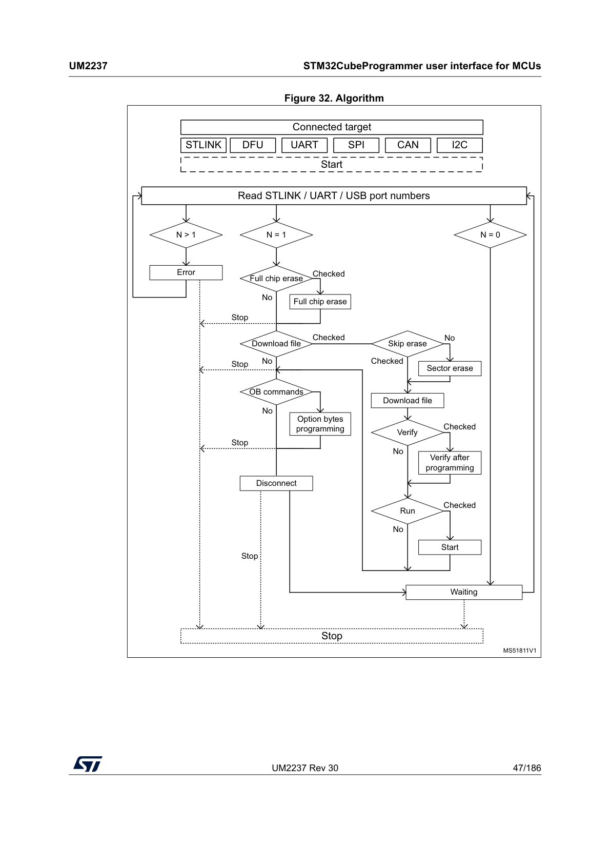
Fig. 30 Algorithm 
Serial numbering 
The automatic mode can be performed with this feature enabled, granting the user the capability to assign unique identifiers to targets in a sequential manner, for tracking and reference purposes. Four fields are needed:
Address: contains the serial numbers.
- Initial data: hexadecimal number, incremented sequentially by 1 for each
target in the automatic mode.
Size: the number of bytes used for the serial numbering.
- Endianness: the user can choose little- or big-endian for the increment
(default is little-endian).
When the maximum serial number for the input size is reached, the automatic mode stops, and the user is asked to click the Stop button.
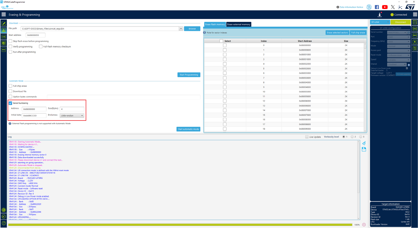
Fig. 31 Automatic mode with serial numbering 