
 STM32CubeProgrammer

J-Link connection 
Segger J-link/Flasher library 
The Segger J-link/Flasher library is not mandatory for using STM32CubeProgrammer with other interfaces. If you want to build your own package without using it, the library can be deleted without impact on STM32CubeProgrammer.
Linux install 
When connecting to an STM32 device over USB on Linux, install the libusb development package first:
sudo apt-get install libusb-1.0.0-dev
If you use ST-LINK, J-Link, or USB DFU, copy the rule files from the
Driver/rules
directory into
/etc/udev/rules.d/
on Ubuntu so the host can access the device correctly.
sudo cp *.* /etc/udev/rules.d
Note
STM32CubeProgrammer requires libusb version 1.0.12 or later.
Docker and Ubuntu 
For USB DFU inside Docker, install the device rules on the host machine and start the container with device access enabled so it can reach the host USB devices and receive udev events.
docker run -v /dev:/dev --device /dev:/dev --net=host
VirtualBox 
For better behavior in a VirtualBox virtual machine, switch the USB controller to USB 3.0 (xHCI) in the VM USB settings.
Fedora 
On Fedora, install libusb with:
sudo dnf install libusb1
To install STM32CubeProgrammer on Linux, download and extract the Linux package from the STM32CubeProgrammer website, then run the Linux setup program to complete installation. On Ubuntu 20, the application icon may be disabled by default; if needed, right-click it and choose Allow launching.
Connect command 
-c,


            --connect
Description: Establishes the connection to the device. This command allows the host to open the chosen device port (UART/USB/JTAG/SWD/J-LINK/SPI/CAN/I2C).
J-Link options 
[dLPM / LPM]: Disable or enable debug in Low power mode. The default configuration is enabled for supported devices such as STM32U5, STM32WB, and STM32L4 series.[getAuthID]: Get device identification for STM32U5 series only. This is a 32-bit device-specific quantity that can be read through the JTAG port. This information is used to derive the expected OEM password keys to unlock the device. This command is not applicable when RDP level = 0.[reset=<mode>]: Reset mode. Possible values areSWrst,HWrst, andCrst. The default value isSWrst. When usingURconnection mode, the reset mode isHWrst.HWrst: Hardware reset performed by the ST-LINK, which physically drives the MCUNRSTpin. The ST-LINKNRSTpin must be connected to the MCU.SWrst: Software reset through Cortex registers.Crst: Core reset through Cortex registers.
[sn=<serialNumber>]: Serial number of the debug probe. Use this option to connect to a specific ST-LINK probe when you know its serial number.[mode=<mode>]: Connection mode. Values areNORMAL,UR, orHOTPLUG. The default value isNORMAL.NORMAL: The target is reset, then halted. The reset type is selected using the Reset mode option.UR: Connect Under Reset mode enables connection to the target using a reset vector catch before executing any instructions. This is useful, for example, when the target contains code that disables the JTAG or SWD pins.HOTPLUG: Hot Plug mode enables connection to the target without halt or reset. This is useful when updating RAM addresses or IP registers while the application is running.
[ap=<accessPort>]: Access port index. The default access port value is0.[speed=]: Connection speed. The default value isReliable. This option is available only for Cortex-M33.Reliable: Allows the user to connect in slow mode.Fast: Allows the user to connect in fast mode.
Example using J-Link debug port 
To connect using port connection mode with ST-LINK probe, it is necessary to mention the port name with at least the connect command (for example:
-c


            port=JLINK
).
Note
Only Flash and Option Bytes (OB) programming are supported via J-Link. Other features are not supported, e.g RDP regression with password, Debug Authentication, Security features. There are other parameters used in connection with the J-Link debug port that have default values. See the Help menu of the tool for more information about default values.
The example below shows a connection example with an STM32 with device ID
0x480.

Fig. 154 Connect operation using J-Link debug port 
The corresponding command line for this example is
-c


            port=JLINK


            ap=0
.
In the connect command (
-c


            port=JLINK


            ap=0
):
The
portparameter is mandatory.The default frequency value is
4000.
Note
To connect to access port 0, the
ap
parameter is used in this example. Any command used after the connect command is then established through the selected access port.
Target configuration panel 
This is the first panel to look at before connecting to a target. It allows the user to select the target interface, either the debug interface using an ST-LINK or J-Link debug probe, or the bootloader interface over UART, USB, SPI, CAN, or I2C.
With the refresh button, the user can check the interfaces available on the PC. If this button is pressed while the ST-LINK or J-Link interface is selected, the tool checks the connected ST-LINK or J-Link probes and lists them in the Serial numbers combo box. If the UART interface is selected, it checks the available communication ports on the PC and lists them in the Port combo box. If the USB interface is selected, it checks the USB devices connected in DFU mode and lists them in the Port combo box. Each interface has its own settings that must be configured before connection.
J-Link settings 
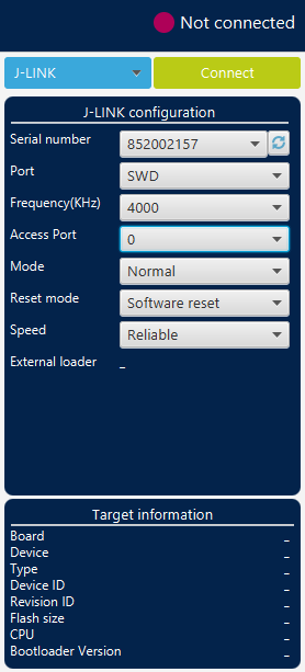
Fig. 155 J-Link configuration panel 
Serial number: this field contains the serial numbers of all connected J-Link probes. The user can choose one of them based on its serial number.
Port: J-Link probe supports only the SWD debug protocol.
Frequency: SWD clock frequency. Only
4000 kHzis available.Access port: selects the access port to connect to. Most STM32 devices have only one access port, access port 0.
Mode:
Normal: the target is reset, then halted. This is selected using the Reset mode option.
Connect under reset: enables connection to the target using a reset vector catch before executing any instructions. This is useful, for example, when the target contains code that disables the SWD pins.
Hot plug: enables connection to the target without a halt or reset. This is useful when updating RAM addresses or IP registers while the application is running.
Reset mode:
Software system reset: resets all STM32 components except the Debug block through the Cortex-M application interrupt and reset control register (AIRCR).
Hardware reset: resets the STM32 device through the
nRSTpin. The RESET pin of the SWD connector (pin 15) must be connected to the device reset pin.Core reset: resets only the Cortex-M through the reset control register.
Speed (Cortex-M33 only):
Reliable: allows the user to connect in slow mode.
Fast: allows the user to connect in fast mode.
External loader: displays the name of the external memory loader selected in the External loaders panel accessible from the main menu (Hamburger menu).
Additional articles 
For more information about the Segger J-link/Flasher library, please refer to the Segger website.